AI-ASSISTED CNC WORKFLOW
AI CNC Programming: The Complete Guide — How AI Turns 2D Drawings into Verifiable G-code
01What is AI-assisted CNC programming?
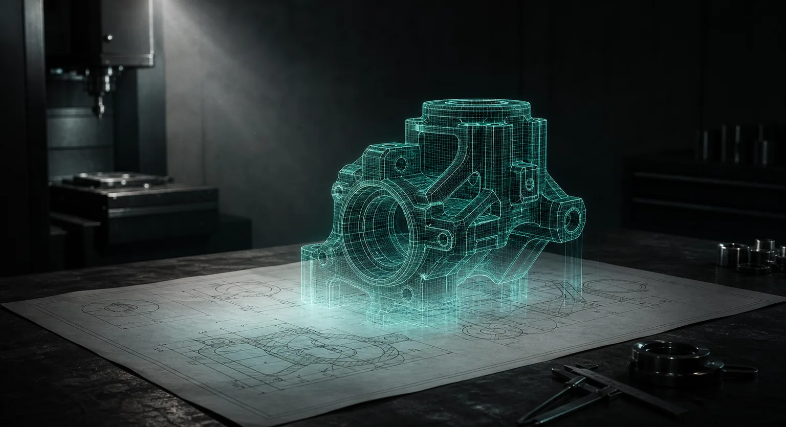
AI CNC programming (also called automated CNC programming, AI CAM, or CNC auto-programming) refers to the technology of using AI models to automatically convert a customer's 2D engineering drawing into a 3D model and an executable CNC machining program (G-code), and to verify it with cutting simulation and dimensional cross-checking. It spans four stages: drawing parsing, 3D modeling, toolpath and G-code generation, and simulation verification.
In the traditional definition of computer-integrated manufacturing (CIM), the core value of CAD/CAM is precisely to seamlessly convert design information into manufacturing instructions, reducing the errors and waiting caused by manual translation[2]. AI CAM is an extension of this path: the modeling, tool selection and plunge strategies that a CAM engineer used to operate step by step are now drafted automatically by AI based on drawing features and the in-house knowledge base, and the person's role shifts from "operating cell by cell" to "reviewing and correcting."
02Three major bottlenecks in the traditional CNC machining-preparation workflow
Classic manufacturing-engineering textbooks point out that the quality and cost of CNC machining depend heavily on "pre-machining preparation"—process planning, tool selection and program verification—not just on the accuracy of the machine itself (Kalpakjian & Schmid, 2020)[1]. Small and mid-sized CNC job shops in Taiwan commonly face three bottlenecks:
- Drawing reading and modeling are time-consuming: customers mostly provide only 2D drawings (DWG, PDF, even photos), and engineers must manually rebuild the 3D model—a medium-complexity plate part can easily take several hours.
- Programming knowledge is concentrated in a few veteran masters: know-how such as plunge order, cutting parameters and controller header codes is hard to document, so staff turnover causes quality fluctuations—exactly the "process-knowledge standardization" problem repeatedly emphasized in the automation literature (Groover, 2019)[2].
- Errors are found too late: misread dimensions or wrong tool-length settings are often not discovered until the test cut, or even a crash, with high rework and machine-downtime costs.
The value proposition of AI CAM is precisely to convert these three bottlenecks into "automatic modeling," "knowledge-base-driven program generation" and "pre-machining simulation verification," respectively.
03From 2D drawing to 3D model: how AI feature recognition works
Machining feature recognition has been a topic of CAD/CAM integration research for over thirty years; in recent years deep-learning methods have made breakthroughs—the FeatureNet proposed by Zhang et al. uses a 3D convolutional neural network to recognize milling features (holes, slots, islands, pockets, etc.), reaching about 96.7% recognition accuracy on a benchmark dataset (Zhang, Jaiswal & Rai, 2018)[5]. This means "having AI understand the machining features on a drawing" already has a feasible basis both academically and in engineering.
In practice, the accuracy of AI drawing reading is directly related to input quality:
- DWG / native electronic drawings: dimension callouts, hole locations and tap specs are all structured data, so recognition accuracy is highest—prefer these.
- PDF or scanned drawings: require vectorization and OCR first, and special symbols and tolerance frames need focused review.
- Phone photos: shadows, perspective and overlapping lines can cause AI to misjudge through-holes or blind holes; these are an auxiliary means and must be confirmed by a person.
Tolerance interpretation is another critical boundary. Dimensions without individual tolerance callouts are usually handled per the ISO 2768 general tolerances[9]; but special tolerances, geometric tolerances (GD&T) and datum settings involve assembly intent and should still be confirmed by an engineer for now. High-precision hole locations can be marked with an agreed color on the drawing to improve the reliability of AI recognition.
04Automatic G-code generation and in-house tool-library integration
G-code (the numerical-control program format specified by ISO 6983) has been developed since the 1950s and is still the universal language of CNC machines[8]. However, academia has long pointed out its limitations: G-code describes only tool motion and preserves neither design intent nor process information, which leads to dialect differences between controllers and makes programs hard to share directly (Xu & Newman, 2006)[7]. This is exactly the technical root of "AI-generated G-code cannot blindly go on the machine directly."
A reliable AI CAM system must incorporate in-house conditions into the generation workflow:
| In-house knowledge | Impact on G-code generation |
|---|---|
| Dedicated tool library (codes, lengths, cutting parameters) | AI selects tools that actually exist, reducing tool-length setup errors and crash risk |
| Machine controller model (FANUC, Mitsubishi, Heidenhain, etc.) | Header codes, canned cycles and dialects are output per the controller |
| Travel and spindle-speed limits | Checked during generation to avoid programs beyond the machine's capability |
| Historically successful programs | AI learns the shop's habitual plunge strategies and machining patterns, gradually approaching the veteran masters' approach |
Authoritative texts on cutting mechanics and CNC design also warn: the choice of feed, speed and depth of cut must be based on the mechanics and vibration characteristics of the tool–workpiece system, or else you get, at best, poor tool marks and accuracy, and at worst broken tools and crashes (Altintas, 2012)[3]. Therefore AI-generated parameters should be bounded by the shop's standard parameter table, rather than letting the model improvise freely.
05Cutting simulation and the "AI verifies AI" double check
A review by CIRP (the International Academy for Production Engineering) points out that virtual-machining technology can simulate material removal and predict collisions and overcuts before running on the machine, a key means of reducing test-cut cost and shortening adoption time (Altintas et al., 2014)[4]. A practical workflow should include two layers of verification:
- Geometry / path verification: preview the toolpath with 3D cutting simulation, checking for overcuts, residual stock, fixture interference and travel overruns.
- Dimensional cross-verification (AI verifies AI): after the 3D model is generated, a second independent AI compares the model dimensions with the 2D drawing callouts one by one and proactively flags anomalous items, reducing manual review time and the miss rate.
This architecture of "a generating model + an independent checking model" echoes the smart-manufacturing literature's recommendation for deep-learning systems: the output of a single model must be verified by an independent mechanism to build trust on the manufacturing floor (Wang et al., 2018)[6].
06Human-in-the-loop: why the master is still the last gate
The correct positioning of AI CAM is to "amplify the master's capacity," not to replace the master. The following judgments still belong to on-site expertise:
- the allocation of roughing / finishing, and clamping and flipping strategies;
- on-the-spot workarounds for doing five-axis methods on a three-axis machine, such as pin alignment and manual flip-and-measure;
- final confirmation of different controllers' header codes and the on-site machine state (tool wear, fixture rigidity).
In other words, AI handles drawing reading, modeling, code generation and cross-verification; on-site experts handle tolerances, datums, special machining methods and the final sign-off before running. Each does what it is best at, and the overall workflow is actually more reliable than either all-manual or all-automatic.
07NDA and security: the necessity of on-premise deployment
Customer drawings are a job shop's most sensitive asset. For NDA-covered or highly confidential products, uploading drawings to a networked public AI service constitutes a leak risk. The countermeasure is to keep drawings in the customer-designated environment, with AI reading them by calling an enterprise-grade model service over an encrypted channel that, per the commercial terms, does not retain them or use them for training; a fully offline on-premise deployment is on the roadmap, assessed against on-site needs — at which point the AI model would be installed on a dedicated in-house server running independently, so drawings, product specifications and customer names never leave the shop.
Institutionally, you can build network-segment isolation and access control against the IEC 62443 industrial-control security series of standards[10], making "the AI server does not connect to the external network, and drawing data does not land in the cloud" an auditable management fact rather than a verbal promise. This is especially important for shops taking supply-chain orders in semiconductor equipment, defense and aerospace.
08Five practical steps to adopt AI CAM
- Inventory drawing sources and quality: tally the proportion of DWG / PDF / photos among customer drawings to decide the starting point of the recognition workflow.
- Import the tool library and standard parameters: file tool codes, standard lengths, cutting parameters and machine travel / spindle-speed limits first, so AI generation is constrained.
- Run a controlled pilot with real drawings: pick a real, medium-complexity plate part and go through the full "drawing → 3D → G-code → simulation → master review" workflow, measuring the machine hours saved.
- Establish review sign-off points: specify which nodes of the AI output must be confirmed by a person (tolerances, datums, before running on the machine) and write them into the SOP.
- Choose the deployment mode by confidentiality level: for general cases, drawings stay in the customer-designated environment and, per the commercial terms, AI reading neither retains them nor uses them for training; a fully offline on-premise deployment for NDA cases is on the roadmap, with network isolation checked per IEC 62443.
09FAQ
Can AI-generated G-code be run on the machine directly?
Not recommended. Different shops have different controller dialects, header codes and clamping conditions, so AI-generated G-code should first pass cutting simulation and review by a senior technician, confirming tool-length compensation, approach/retract moves and travel safety before it goes on the machine.
How accurate is AI at reading 2D drawings and converting them to 3D models?
Accuracy is highest with native electronic drawings such as DWG; the system recognizes dimensions, hole locations, tapped holes and standard features and generates a 3D model, then a second AI cross-checks the original drawing dimensions and proactively flags anomalies. Photographed drawings still warrant manual confirmation of through-hole / blind-hole interpretation.
If customer drawings are under NDA, will using AI leak them?
Networked public AI should not be used to process confidential drawings. Drawings stay in the customer-designated environment and, per the commercial terms, AI reading neither retains them nor uses them for training; a fully offline on-premise deployment is on the roadmap, assessed against on-site needs — at which point you would compute independently in-house, drawings never leave the shop, and you can build auditable security controls against IEC 62443.
Can AI CAM work with the shop's existing tool library and Mastercam?
Yes. First import tool codes, lengths and cutting parameters so that AI generation and simulation select the correct tools; it can also be integration-tested with existing workflows such as Mastercam and Lifecad, learning from past successful programs.
Get notified when new articles and video briefings go live—no inbox spam, unsubscribe in one click. (newsletter in Chinese)
READY FOR A CONTROLLED PILOT?
Use one real drawing to see how far AI CAM can go
From drawing quality, machine controllers and tool libraries to security requirements, we help define the adoption approach that fits your shop.
Contact an onboarding advisor Training courses10References
- Kalpakjian, S., & Schmid, S. R. (2020). Manufacturing Engineering and Technology (8th ed.). Pearson.
- Groover, M. P. (2019). Automation, Production Systems, and Computer-Integrated Manufacturing (5th ed.). Pearson.
- Altintas, Y. (2012). Manufacturing Automation: Metal Cutting Mechanics, Machine Tool Vibrations, and CNC Design (2nd ed.). Cambridge University Press.
- Altintas, Y., Kersting, P., Biermann, D., Budak, E., Denkena, B., & Lazoglu, I. (2014). Virtual process systems for part machining operations. CIRP Annals, 63(2), 585–605.
- Zhang, Z., Jaiswal, P., & Rai, R. (2018). FeatureNet: Machining feature recognition based on 3D Convolutional Neural Network. Computer-Aided Design, 101, 12–22.
- Wang, J., Ma, Y., Zhang, L., Gao, R. X., & Wu, D. (2018). Deep learning for smart manufacturing: Methods and applications. Journal of Manufacturing Systems, 48, 144–156.
- Xu, X. W., & Newman, S. T. (2006). Making CNC machine tools more open, interoperable and intelligent — a review of the technologies. Computers in Industry, 57(2), 141–152.
- ISO 6983-1:2009. Automation systems and integration — Numerical control of machines — Program format and definitions of address words. International Organization for Standardization.
- ISO 2768-1:1989. General tolerances — Tolerances for linear and angular dimensions without individual tolerance indications. International Organization for Standardization.
- IEC 62443 series. Industrial communication networks — Network and system security. International Electrotechnical Commission.
Further reading: AI CNC Platforms Compared: the 2026 Landscape and How to Choose