DRAWING RECOGNITION · LIMITS & STRENGTHS
Can a Phone Photo Build a 3D Model? What AI Drawing Recognition Can and Can't Do
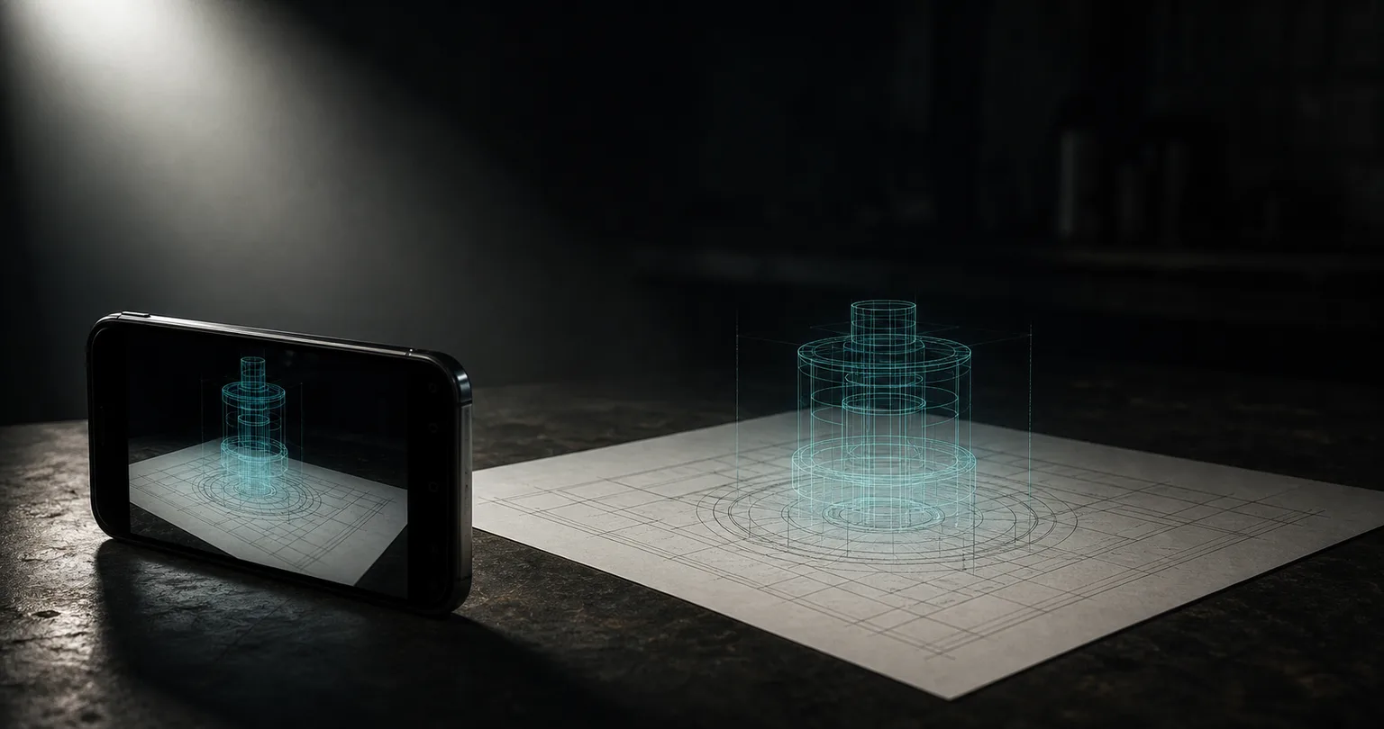
01What is AI drawing recognition (2D-to-3D)?
2D-to-3D (drawing-recognition AI) means using an AI model to read the 2D engineering drawing a customer provides, recognize the dimension callouts, hole positions, threaded holes, and machining features in it, and then automatically generate the corresponding 3D model. For most Taiwan CNC job shops, the customer often gives only a 2D drawing—it might be a DWG electronic file, a PDF, or even a phone shot of a paper print—and DWG-to-3D is the most accurate path among them. This step once relied on engineers rebuilding by hand, and a plate of medium complexity could easily eat up hours.
Classic manufacturing-engineering textbooks note that machining quality and cost depend heavily on "pre-machining preparation"—reading the drawing, planning the process, and building the model—not just the accuracy of the machine itself[3]. The purpose of drawing-recognition AI is to turn this time-consuming preparation from "redrawing line by line" into "the AI drafts, the human reviews." But to use it safely, you first have to be clear about what it can and can't do.
02What AI can do: the technical basis of machining feature recognition
Machining feature recognition has been a subject of CAD/CAM integration research for more than thirty years, and it has broken through recently thanks to deep learning. The FeatureNet proposed by Zhang et al. recognizes milling features (holes, slots, islands, pockets, and so on) with a 3D convolutional neural network, reaching about 96.7% recognition accuracy on a benchmark dataset[1]. This means "getting AI to understand the standard machining features on a drawing" already has a solid foundation both academically and in engineering.
In a job shop's everyday language, what drawing-recognition AI can reliably do today is roughly:
- recognize regular machining features: round holes, counterbores, drilled holes, square slots, pockets, and outer profiles;
- read structured dimension and hole-position callouts and generate the corresponding 3D model draft;
- recognize standard threaded-hole specs and common callout conventions;
- have a second, independent AI cross-check the generated 3D model's dimensions against the original drawing one by one, proactively flagging inconsistent items.
It's worth stressing that the roughly 96.7% figure is a "feature-recognition accuracy on a benchmark dataset"—it represents technical feasibility, not a score any given real customer drawing will achieve. Actual accuracy is hugely affected by input quality, which is exactly the focus of the next section.
03DWG, PDF, photo: how the three inputs differ in accuracy
Feed the same drawing to the AI in different formats and the results can differ wildly. The closer the input is to native CAD data, the more reliable the recognition:
| Input form | Accuracy | Handling and cautions |
|---|---|---|
| DWG / native electronic file | Highest | Dimensions, hole positions, and threaded holes are all structured data; DWG-to-3D reads the geometry directly—provide it first |
| PDF / scanned drawing | Medium | Needs vectorization and OCR first; special symbols, tolerance frames, and tiny callouts warrant focused review |
| Phone photo | Supplementary level | Shadows, perspective distortion, and overlapping lines easily cause misreads; a supplementary means whose read results must be confirmed by a person |
So back to that often-asked question—"Can a phone photo build a 3D model?" The answer is: technically you can try, but it shouldn't be your only source. A photo can help an engineer sketch a quick draft, but it isn't enough to support machine-ready reliability. The most effective step toward stable DWG-to-3D quality isn't in the algorithm but at the source: ask the customer to provide the native electronic file whenever possible.
04What AI can't do: shadows, perspective, and through-hole/blind-hole misreads
Talking honestly about what it "can't" do is the real value of this article. Phone-shot drawings have a few inherent problems that directly affect how drawing-recognition AI reads them:
- Shadows and glare: paper creases and lighting shadows get mistaken for lines or callouts, letting the AI read in features that don't exist at all.
- Perspective distortion: when not shot straight on, circles become ellipses and straight lines tilt, distorting dimensional proportions.
- Through-hole/blind-hole misreads: in a 2D view, the difference between a through-hole and a blind hole is often conveyed only by section lines or a single depth callout; once a photo is blurry or has glare, the AI may well read a blind hole as a through-hole, and the hole depth is then wrong.
- Overlapping lines: when dense callouts and dimension lines cross, OCR easily misplaces the numbers.
These aren't problems a "smarter model" can solve in one shot—they are physical limits of the input information itself. So for any job with a photo as input, the AI-generated 3D model should be treated as a "draft pending confirmation," released only after an engineer has checked hole depth, hole type, and key dimensions item by item. This is exactly why we write human-in-the-loop into the standard workflow rather than treating it as an optional step to skip.
05Tolerances, GD&T, and datums: the final gate of human review
Even with a clean DWG, there's one class of information that shouldn't be left entirely to the AI—tolerances and datums. Dimensions not individually toleranced are usually handled per ISO 2768 general tolerances[2], and the AI can apply that by rule up front; but the following judgments involve assembly intent and functional requirements, and today they remain the engineer's professional domain:
- Special tolerances: individual callouts tighter than the general tolerance, which decide tool selection, cutting strategy, and measurement strategy;
- Geometric tolerances (GD&T): flatness, position, coaxiality, and so on, which govern how the part behaves in assembly;
- Datum settings: which face or axis serves as the measurement reference, which directly affects machining sequence and clamping.
Manufacturing-engineering textbooks also caution that the choice of tolerances and measurement datums is a key link that determines the machining method and cost, not a mere copying of dimensions[3]. In practice there's a simple, effective approach: for high-precision hole positions or key features, mark them on the drawing with an agreed color—this raises the AI's reliability in recognizing those features and, at the same time, plants a flag in the workflow reminding the engineer to review those spots closely.
06A practical workflow within honest limits
Gathering the "can and can't" above into an executable workflow, the correct way to use drawing-recognition AI in a job shop is this:
- Ask for DWG at the source first: if you can get the native electronic file, don't use a photo—DWG-to-3D is the bedrock of accuracy.
- Route by format: vectorize and OCR PDFs first; use photos only as a supplement, and mark them as jobs pending human confirmation.
- AI generates a 3D draft: recognize standard machining features, hole positions, and dimensions, quickly producing a model draft.
- A second AI cross-checks: an independent model matches the 3D dimensions against the original drawing's callouts one by one, proactively flagging anomalies and shortening human review time.
- The engineer confirms the line: tolerances, GD&T, datums, through-hole/blind-hole, and special processes get the final sign-off from a professional before moving on to G-code and simulation.
This workflow neither overstates that AI can finish everything in one click nor denies that it can save a great deal of rebuilding time. Its value lies in putting AI on the repetitive reading it's best at and keeping the engineer on the line where judgment is most needed—which is precisely the most pragmatic division of labor once you've thought through what it "can and can't" do. To go further on how a 3D model feeds down into a verifiable machining program, see "The Complete Guide to CNC Auto-Programming: How AI Turns a 2D Drawing into Verifiable G-code." To learn how drawing reading accelerates quoting, see "How AI Speeds Up CNC Quoting and Manufacturability Review." If you're interested in the overall use cases, read "Generative AI on the Factory Floor: 7 Practical Use Cases and Limits for CNC Machining."
07FAQ
Can AI build a machinable 3D model automatically from a single phone photo of a drawing?
A photo can serve as a supplementary input, but it's not advisable as the sole source. Phone shots often have shadows, perspective distortion, and overlapping lines, which easily lead the AI to misread through-holes versus blind holes or misplace a callout. The most reliable approach is to provide a native DWG electronic file; if you only have a photo, the AI-generated 3D model must be checked item by item by an engineer for hole depth and dimensions before it can be used.
Among DWG, PDF, and photo inputs, how does AI drawing-reading accuracy differ?
Native electronic files such as DWG carry dimensions, hole positions, and threaded holes as structured data, giving the highest recognition accuracy—use them first. PDFs or scanned drawings need vectorization and OCR first, with special symbols and tolerance frames warranting focused review. Phone photos are a supplementary means, and their read results must always be confirmed by a person. The closer the input is to native CAD, the more reliable the AI.
Can AI also read tolerances and geometric tolerances (GD&T) automatically?
For dimensions not individually toleranced, the AI can handle them up front per ISO 2768 general tolerances; but special tolerances, geometric tolerances (GD&T), and datum settings involve assembly intent and should still be confirmed by an engineer today—they can't be left entirely to the model. High-precision hole positions can be marked on the drawing with an agreed color to raise the AI's recognition reliability and flag the spots for focused human review.
Can AI drawing recognition replace the modeling engineer?
The role is to accelerate, not replace. The AI turns 2D drawings into a 3D model draft quickly and recognizes standard machining features, then a second AI cross-checks dimensions and proactively flags anomalies; the engineer focuses on tolerances, datums, special processes, and final confirmation. With that division of labor, the whole is more reliable than either all-manual rebuilding or fully automated release.
Get notified when new articles and video reviews go live—no inbox flooding, one-click unsubscribe.
TEST IT WITH YOUR OWN DRAWING
Take a drawing you have on hand and see how accurately AI reads it
Whether it's a DWG, a PDF, or a phone photo, we help you assess the feasibility of drawing recognition and the line of human review, running one full 2D-to-3D flow.
Talk to an onboarding consultant Training courses08References
- Zhang, Z., Jaiswal, P., & Rai, R. (2018). FeatureNet: Machining feature recognition based on 3D Convolutional Neural Network. Computer-Aided Design, 101, 12–22.
- ISO 2768-1:1989. General tolerances — Tolerances for linear and angular dimensions without individual tolerance indications. International Organization for Standardization.
- Kalpakjian, S., & Schmid, S. R. (2020). Manufacturing Engineering and Technology (8th ed.). Pearson.