APPLICATION SCENARIO · AUTOMATION EQUIPMENT
Machining Automation-Equipment Parts: An AI CNC Answer for High-Mix, Low-Volume, Rush Deadlines
01What Makes Machining Automation-Equipment Parts Its Own Kind of Job
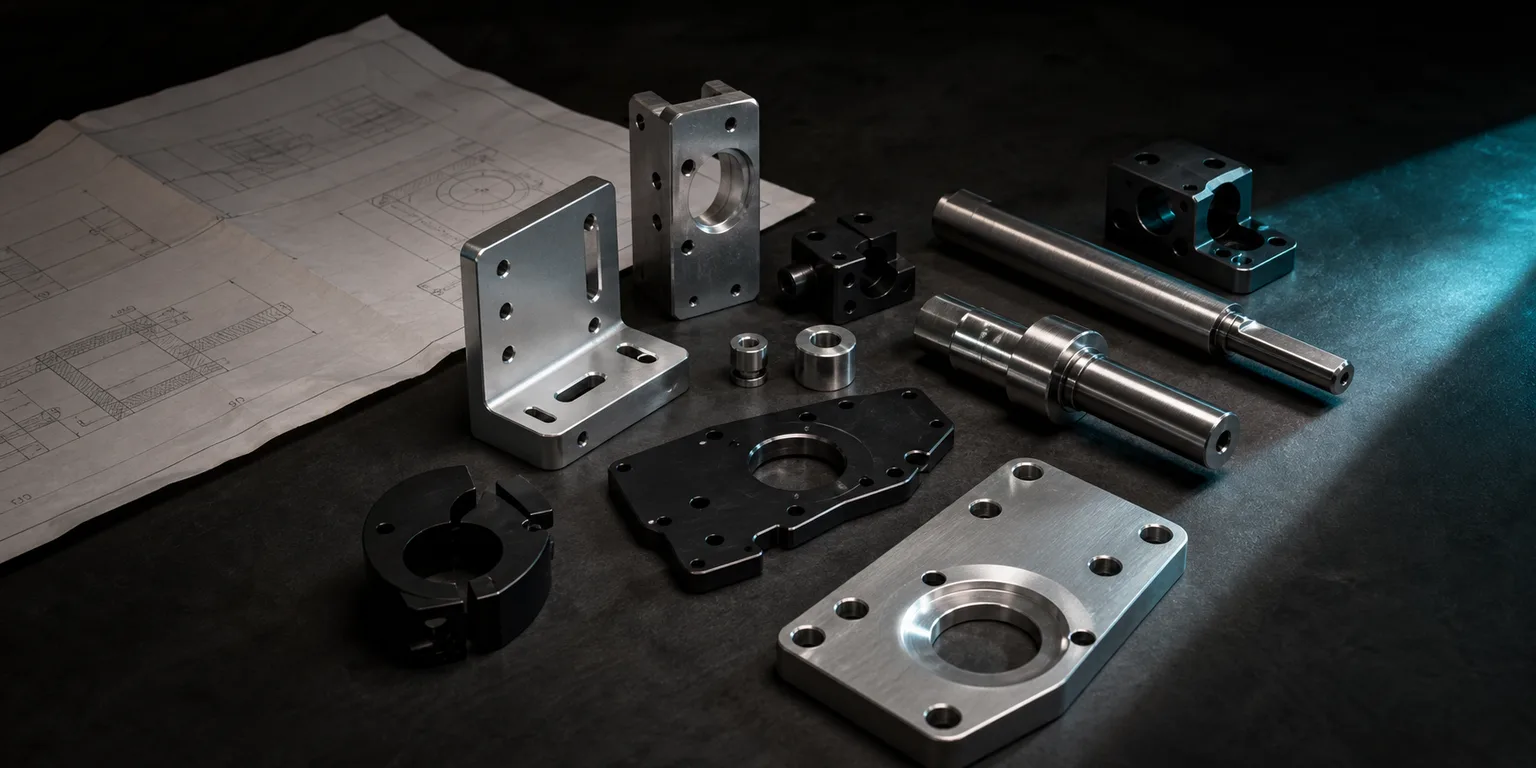
Automation equipment parts machining refers to machining mechanical parts made for production-line equipment, fixture modules, robot-arm peripherals, conveyance and positioning mechanisms, and the like. It's fundamentally different from high-volume contract work for automotive or consumer electronics—the typical traits of this kind of equipment parts machining are:
- Mechanical parts are high-mix, low-volume: a design often runs only a few to a few dozen pieces, yet the number of distinct items is enormous—almost every drawing is new.
- Drawing sources are messy: native DWG files, STEP 3D models, PDFs, and even a hand sketch a mechanical engineer dashed off can all show up at once.
- The deadline is often "needed yesterday": one missing part stalls an entire machine, so rush jobs and queue-jumping orders are the norm.
- Designs are revised frequently: during trial assembly and machine tuning, mechanisms often get dimension changes and moved holes, one revision after another.
Manufacturing-systems theory noted long ago that when product variety is high and batches are small, the system's cost and lead-time bottleneck shifts from "machining itself" to non-cutting stages like "prep, changeover, and planning" (Chryssolouris, 2006)[1]. Machining automation-equipment parts is a textbook case of this high-variety, low-volume situation—what really eats the lead time is the prep work behind each new drawing. To get the overall strategy for high-mix, low-volume orders first, read on in An AI Answer for High-Mix, Low-Volume Machining.
02The Four Pain Points Under High-Mix, Low-Volume, Rush Deadlines
Bring those traits down to the shop floor and they become four concrete pain points:
- Every new drawing needs fresh programming: with large batches, programming once amortizes across hundreds or thousands of pieces; equipment mechanical parts run only a few per design, so the one-time prep of reading the drawing, rebuilding the 3D, and drafting the initial toolpath is an enormous share—it's like paying a "prep tax" all over again with every order you take.
- Quotes can't keep up: a rush job needs a price back within hours, but the engineer first has to understand the drawing and estimate the machining scope—just reading the drawing eats most of the time, and a slow quote sends the order to a competitor.
- Drawing-file quality varies: DWG, STEP, PDF, and hand sketches are all mixed together, with uneven formats and annotation quality, so manual interpretation is both slow and prone to misreading through-hole versus blind-hole and tapped-hole specs.
- Revision rework: during mechanism tuning, changing one hole or moving one dimension—if you redo the whole program package—is not only slow but also easy to miss the sections that weren't changed.
Classic texts on automation and production systems stress that if process knowledge is concentrated in a few master machinists and lacks standardization and reuse mechanisms, quality wobbles the moment someone leaves—which is especially fatal in high-variety mechanical-parts machining (Groover, 2019)[2]. The common root of all four pain points is that "prep" hasn't been effectively automated and reused.
03AI Drawing-Reading and Modeling: Bringing Prep Time Down
The most direct value AI CNC brings to high-mix, low-volume work is automating the one-time prep of "read the drawing → rebuild the 3D → draft the initial toolpath." Machining feature recognition has been a topic in CAD/CAM integration for over thirty years, and deep learning has recently made a breakthrough—the FeatureNet proposed by Zhang and colleagues uses a 3D convolutional neural network to recognize milling features (holes, slots, islands, pockets, and so on), reaching about 96.7% recognition accuracy on a benchmark dataset (Zhang, Jaiswal & Rai, 2018)[4]. This means "getting an AI to understand the machining features on a mechanical-part drawing" already has a technically feasible foundation.
In the real workflow of machining automation-equipment parts, AI drawing-reading and modeling shifts the engineer's role from "step-by-step operation" to "review and correction": the AI first drafts a 3D model and preliminary toolpath from the drawing's features and the shop's knowledge base, and the person only needs to confirm and adjust the critical spots. For a mechanical part that runs only a few pieces, the prep hours saved are exactly what decides whether you can ship on time.
04Fast Quoting and Manufacturability Interpretation
The bottleneck in rush-job quoting is usually "you can't estimate before you understand the drawing." After reading the drawing, the AI quickly builds a 3D model and does a first read of machining features, helping estimators grasp the machining scope faster, roughly gauge the number of operations, and spot manufacturability risks, shortening the quoting back-and-forth. Research on computer-aided process planning (CAPP) has long pointed out that turning process planning from purely manual experience into systematic, reusable interpretation is a key direction for shortening prep and planning time (Xu, Wang & Newman, 2011)[3].
The product boundary bears emphasis: what the AI provides is faster interpretation, not automatic pricing. The final price should still be confirmed by a person based on the shop's actual labor hours, material, fixturing, and lead-time cost. To dig into how the quoting process is accelerated by AI, see How AI Speeds Up CNC Lead-Time Estimation and Scheduling.
05Cutting Simulation for Error Prevention and AI Dimensional Cross-Verification
High-mix, low-volume means "no room for a trial cut"—with only a few pieces per design, a crash or gouge can scrap the whole batch and blow the deadline. A review by CIRP (the International Academy for Production Engineering) notes that virtual machining can simulate material removal and predict collisions and gouges before the job goes on the machine, making it a key means of lowering trial-cut cost and shortening ramp-up time (Altintas et al., 2014)[5]. In practice it should include two layers of checking:
- Geometry / path verification: preview the toolpath with 3D cutting simulation and check for gouges, leftover stock, fixture interference, and travel overruns.
- Dimensional cross-verification (AI checking AI): after the 3D model is generated, a second independent AI compares the model's dimensions against the original drawing's callouts one by one and proactively flags anomalies, cutting manual-review time and the miss rate—especially useful for mechanical parts with uneven drawing quality.
Cutting simulation and dimensional cross-verification together add a layer of insurance for high-mix, low-volume orders that "get no chance to trial-and-error"—right before the job goes on the machine.
06Frequent Revisions: Diff Comparison and Fast Rework
Revisions during trial assembly and machine tuning are the norm and a major source of rework cost. AI CNC can compare the differences between the old and new drawings and models, focus on the changed hole positions, dimensions, or features, and regenerate code and simulation only for the affected machining sections rather than redoing the whole program package.
This brings two benefits: it shortens revision-rework time, and it lowers the risk of a missed change—like "changing only dimension A but forgetting it drives hole B." For automation-equipment parts machined one revision after another, fast rework on revision diffs happens even more often than first-piece prep, and the time saved adds up considerably.
07Drawing-Prep Tips for Mechanical Designers
Drawing quality directly determines the reliability of AI drawing-reading—and the lead time. A few practical tips for the mechanical designers sending out the work:
| Recommendation | Why it helps |
|---|---|
| Prefer native DWG files or STEP 3D models | Structured data gives the highest recognition accuracy—better than scanned or photographed PDFs—and directly shortens modeling time |
| Mark standard tapped holes with standard callouts (e.g., M6, thread depth, through-hole/blind-hole clearly noted) | Prevents the AI or a person from misjudging hole type and thread spec, reducing back-and-forth confirmation |
| Clearly mark critical tolerances and datums | Anything not individually marked is handled at general tolerance; marking critical dimensions clearly avoids precision disputes |
| Keep the revision number and change notes on revisions | Makes diff comparison easier so rework touches only the sections that actually changed |
| Use hand sketches only as a supplement, with key dimensions attached | Hand sketches can kick off the conversation, but through-hole/blind-hole and tapped holes still need to be confirmed with a formal file |
For how different drawing-file formats affect machining prep, read on in Common Drawing-File Formats for CNC Machining and Best Practices. In one line: the more native the format and the more standard the annotation, the shorter the lead time.
08FAQ
With high-mix, low-volume work where every drawing is different, can AI CNC really speed up machining prep?
Yes, and the benefit is most pronounced in high-mix, low-volume situations. With large batches, programming once amortizes across many pieces; equipment mechanical parts run only a few per design, so prep hours are an enormous share. AI drawing-reading and modeling automates the one-time prep of "reading the drawing, rebuilding the 3D, drafting the initial toolpath," shifting engineers from step-by-step operation to review and correction—exactly the stage high-mix, low-volume orders most need to compress.
Rush-job quotes are often too slow—what can AI help with?
After reading the drawing, the AI quickly builds a 3D model and does a first read of machining features, helping estimators grasp the machining scope faster, roughly gauge the operations and manufacturability risks, and shorten the quoting back-and-forth. But the final price should still be confirmed by a person based on the shop's actual labor hours, material, and fixturing costs—the AI provides faster interpretation, not automatic pricing.
Designs get revised a lot—does changing one dimension mean redoing the whole package?
No. AI CNC can compare the differences between the old and new drawings and models, focus on the changed hole positions, dimensions, or features, and regenerate code and simulation only for the affected machining sections rather than redoing the whole program package—markedly shortening revision-rework time and lowering the risk of a missed change.
Drawing sources are all over the place—can it read DWG, STEP, and hand sketches?
Recognition reliability depends on input quality. Native DWG files and STEP 3D models have the highest accuracy and are the most recommended; PDFs or scanned drawings need vectorization and OCR, with tolerance frames and special symbols warranting focused review; hand sketches or photos are only supplementary, and through-hole/blind-hole and tapped-hole specs must be confirmed by a person.
Get notified when new articles and video guides go live—no inbox flooding, unsubscribe in one click.
READY FOR A CONTROLLED PILOT?
Take One Real Mechanical Part and See How Many Prep Hours AI CNC Saves
From drawing format and standard tapped-hole callouts to the tool library and your rush-job and revision workflows, we help define a rollout that fits your equipment-parts machining.
Talk to a rollout consultant Training courses09References
- Chryssolouris, G. (2006). Manufacturing Systems: Theory and Practice (2nd ed.). Springer.
- Groover, M. P. (2019). Automation, Production Systems, and Computer-Integrated Manufacturing (5th ed.). Pearson.
- Xu, X., Wang, L., & Newman, S. T. (2011). Computer-aided process planning — A critical review of recent developments and future trends. International Journal of Computer Integrated Manufacturing, 24(1), 1–31.
- Zhang, Z., Jaiswal, P., & Rai, R. (2018). FeatureNet: Machining feature recognition based on 3D Convolutional Neural Network. Computer-Aided Design, 101, 12–22.
- Altintas, Y., Kersting, P., Biermann, D., Budak, E., Denkena, B., & Lazoglu, I. (2014). Virtual process systems for part machining operations. CIRP Annals, 63(2), 585–605.