CAD FILE FORMATS FOR CNC
DWG vs. DXF vs. STEP vs. STL: A Guide to Choosing CAD File Formats for CNC Machining
01Why do CAD file formats affect CNC quoting?
When you hand a drawing to a CNC shop for a quote, the CAD file format they receive often decides the speed and accuracy of that quote before you ever see a number. The reason is simple: the shop must first "understand" your geometry—dimensions, hole locations, tolerances and machining features—before it can estimate machine time, tooling and material. The more complete and structured the information preserved in the file, the faster and less error-prone this interpretation becomes.
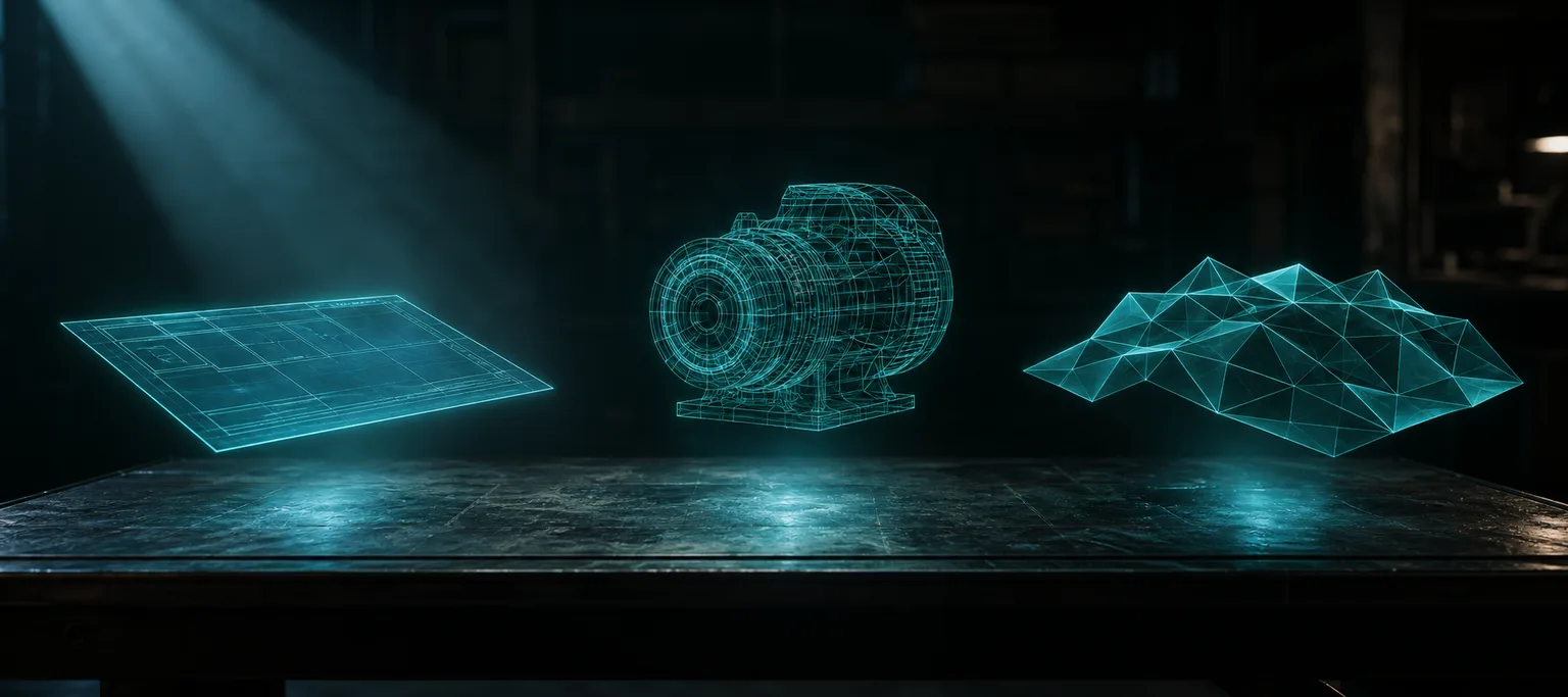
The common file types fall roughly into two groups. 2D drawings (DWG, DXF, PDF) describe the various views of a part with lines, arcs and callouts; 3D files (STEP, STL and the like) describe the solid geometry directly. Understanding what each one "keeps and throws away" directly determines whether you get a precise number or a conservative markup.
022D drawings: how to choose between DWG, DXF and PDF
2D drawings are still the most common language of mechanical machining in Taiwan. The difference between the three common formats comes down to "what shape the information is preserved in":
- DWG: AutoCAD's native format. It is a closed, proprietary format and carries the most complete information—lines, arcs, layers, dimensions and attributes are all stored as vector objects that can be read and measured directly by software.
- DXF: the Drawing Exchange Format, defined by AutoCAD with a published specification. It was designed from the outset for cross-software exchange, so nearly all CAD/CAM tools can open it; the trade-off is that complex objects, custom styles or newer features may be simplified or lost in conversion.
- PDF: distinguish between "vector PDF" and "scanned PDF." A vector PDF is output directly from CAD, so its lines and text can be extracted; a scanned PDF or a photo is essentially an image, and dimensions and tolerances must be read via OCR or by hand, with special symbols and tolerance frames easily misread.
A simple rule of thumb: if the client and the shop can use the same software, DWG preserves the most complete information; for cross-software collaboration, DXF is the most robust for compatibility; PDF is fine as a human-readable reference, but when it is the only machine-input source, it carries the highest interpretation cost.
033D files: the fundamental difference between STEP and STL
Moving into 3D, the two most commonly confused yet most different formats are STEP and STL. Both can show a solid part on screen, but they record it internally in completely different ways, and that difference directly determines whether the file can be used for precision machining.
STEP: structured, exact geometry (B-rep)
STEP (the ISO 10303 standard) describes a solid using "boundary representation (B-rep)": it records exact mathematical surfaces such as planes, cylinders and cones, and how they enclose a closed solid. So a Ø10 hole in a STEP file is an exact cylinder—its radius, depth and position are all readable parameters. This structured data can be fed straight into CAM for toolpath planning, and it can also be cross-checked against the drawing dimensions.
STL: a triangle-mesh surface approximation
STL, by contrast, chops the part's surface into a large number of triangles (a triangle mesh) and keeps only the vertex coordinates and normal vectors of those facets. It was designed for 3D printing (rapid prototyping); its advantages are that it is universal and lightweight, its drawback that surfaces are "polygonized"—a round hole becomes an approximate circle formed by many short straight segments, with no exact radius, no dimension callouts and no machining-feature semantics. Using STL for CNC machining usually means first reverse-engineering or rebuilding the solid, adding an extra step.
One-line mnemonic: STEP tells the machine "this is a cylindrical hole with a 5 mm radius"; STL only tells the machine "there is a ring of very, very short facets forming a hole here." The former is structured design intent; the latter is a discretized shape approximation.
04DWG/DXF/STEP/STL at a glance
| Format | Dimension | Type | Geometric precision | Suitability for CNC machining |
|---|---|---|---|---|
| DWG | 2D/3D | AutoCAD native (closed) | Vector-exact | Ideal for 2D-profile / drilling parts; most complete information |
| DXF | 2D/3D | Open interchange format | Vector-exact (complex objects may be simplified) | Top choice for cross-software 2D delivery |
| STEP | 3D | Structured B-rep (ISO 10303) | Exact surfaces and dimensions | Top choice for 3D parts; directly programmable and measurable |
| STL | 3D | Triangle mesh | Approximate (depends on mesh density) | Mainly for 3D printing; machining usually needs a rebuild |
| PDF (vector) | 2D | Document output | Lines/text extractable | Mainly for reference and human reading; can assist interpretation |
| Photo / scan | 2D image | Raster image | No exact geometry | Least favorable; appearance reference only |
You can see a clear axis: from photo, to scanned PDF, to vector 2D, to structured 3D, the "structured information a machine can read directly" increases step by step, while the information the shop must fill back in by hand decreases step by step.
05The old data-exchange problem: why conversion loses information
Conversion between formats is not lossless. Manufacturing interoperability is a problem that has been studied for decades in the CNC field: different CAD/CAM/CNC systems each have their own internal data models, and when they exchange through an intermediary format, design intent and process information are often diluted or lost in the conversion[1]. This is exactly why neutral standard formats like STEP have been promoted—using a single open, standardized data model reduces the fragmentation of needing "a dedicated conversion pipeline between every pair of software tools."
An even more fundamental gap occurs at the "semantic level" of the data. The computer-aided process planning (CAPP) literature points out that an ideal manufacturing data flow should preserve features and process intent, not just geometric shape; yet in practice many interchange formats convey only shape, leaving process semantics such as "this is a hole to be tapped" or "this face is a datum" behind in the native system[2]. At the machine end, what the controller ultimately executes is G-code—the numerical-control program format defined by ISO 6983, which describes only the tool's motion path and carries no design intent whatsoever[3].
Connecting the chain: as information travels down from "CAD file → interchange format → G-code," its semantics steadily diminish[1]. So the more structured the file the upstream side hands off, the more room the downstream side has to automate; conversely, give only a photo, and the missing information has to be filled back in by hand at every stage.
06Quoting and AI drawing reading: which file is best?
Back to the most practical question: to send for a quote, or to hand to AI for drawing reading and modeling, which file should you provide? Following the logic above, the answer is clear—the more structured and native the electronic file, the better:
- Most favorable: native electronic drawings (DWG/DXF) and STEP. Dimension callouts, hole locations, tap specs and exact geometry are all structured data that software can read directly, so AI drawing reading achieves the highest accuracy when recognizing machining features, and quoting is fastest.
- Next: vector PDF. Lines and text can be extracted, but tolerance frames and special symbols still need focused review.
- Then: STL. It conveys shape but lacks exact dimensions and feature semantics, so the solid usually has to be rebuilt before programming.
- Least favorable: photos and scans. Shadows, perspective distortion and overlapping lines make through-holes / blind holes and exact dimensions hard to read; they can only serve as an auxiliary reference for appearance and machining features.
This is also the consistent recommendation of our AI drawing-reading workflow: prefer native electronic drawings such as DWG, use PDF and photos as auxiliaries, and after modeling let a second AI cross-check the 3D model dimensions against the original drawing and proactively flag anomalies; tolerances, datums and special machining methods are left for on-site engineers to confirm. Further reading: "Can a Phone Photo Build a 3D Model? What AI Drawing Recognition Can and Can't Do", the full workflow in "The Complete Guide to CNC Auto-Programming", and the machine-end program format in "G-code: A Complete Introduction".
07FAQ
Which is better for CNC machining, STEP or STL?
Prefer STEP. STEP records exact geometry as B-rep, preserving planes, cylinders, hole locations and dimensions, and can be programmed and measured directly; STL is only a triangle-mesh surface approximation with no exact radii or dimensions, is mainly used for 3D printing, and often still requires rebuilding a solid model for machining.
What is the difference between DWG and DXF?
DWG is AutoCAD's native, closed format and carries the most complete information; DXF is an open format designed for cross-software exchange with the best compatibility, but complex objects and custom styles may be simplified in conversion. Use DWG within the same software, DXF for cross-software collaboration.
Can you quote from only a PDF or a paper drawing?
Yes, but it is slower and more prone to misreading. A vector PDF's lines and text can be extracted; scans and paper are equivalent to images, so dimensions and tolerances must be read by hand or OCR. When a DWG/DXF or STEP is available, drawing reading, modeling and quoting are all faster and more accurate.
If the customer only provides photos, can AI build a model?
Photos are the least favorable of all inputs. Perspective distortion and shadows make through-holes / blind holes and exact dimensions hard to read; they can only serve as an appearance reference and still need to be paired with a dimensioned drawing, with an engineer confirming the critical dimensions and tolerances.
Get notified when new articles and video briefings go live—no inbox spam, unsubscribe in one click. (newsletter in Chinese)
GOT A DRAWING TO QUOTE?
Hand your drawing to AI and machinists who understand manufacturing, and see it clearly sooner
Whether you have a DWG, DXF, STEP or a single photo in hand, we help define the most suitable drawing-reading and quoting workflow—native electronic drawings are the most favorable, and other formats can still assist interpretation.
Contact an onboarding advisor Training courses08References
- Xu, X. W., & Newman, S. T. (2006). Making CNC machine tools more open, interoperable and intelligent — a review of the technologies. Computers in Industry, 57(2), 141–152.
- Xu, X., Wang, L., & Newman, S. T. (2011). Computer-aided process planning — A critical review of recent developments and future trends. International Journal of Computer Integrated Manufacturing, 24(1), 1–31.
- ISO 6983-1:2009. Automation systems and integration — Numerical control of machines — Program format and definitions of address words. International Organization for Standardization.