CRASH PREVENTION & VERIFICATION
What Does One CNC Crash Really Cost? How Cutting Simulation and AI Verification Stop It Before the Job Runs
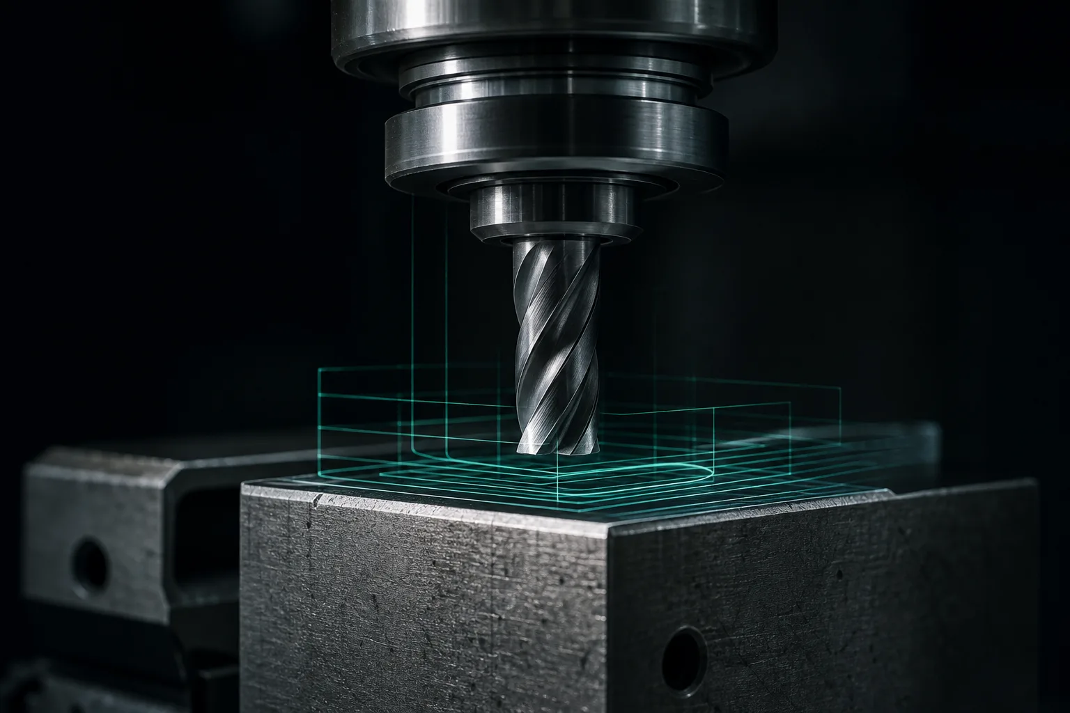
01What do you lose in one crash? Add up the cost categories first
A CNC crash is when the tool, spindle or fixture collides with the workpiece, fixturing or machine structure along an unintended path. Most people's first thought is "how much to fix the spindle," but the real loss is a chain of knock-on costs worth breaking out one by one:
- Machine and spindle repair: an impact can throw the spindle out of true, damage bearings or lose accuracy; in bad cases it needs servicing or even replacement, and the machine produces nothing while it's down.
- Scrapped tools and workpieces: broken tools and chipped edges are inevitable; a half-finished workpiece that already has hours in it is often scrapped along with it, and the loss of expensive material can be substantial.
- Downtime and lost capacity: from clearing the scene and checking accuracy to re-touching-off and re-running a trial cut, the time the machine is offline is an invisible but real cost.
- Delivery and trust: once the schedule is thrown off and a delivery date slips, your commitment to the customer and their confidence in future orders can both be affected — the item hardest to measure by a repair bill.
In other words, the cost of a crash is the sum of "repair + scrap + downtime + delivery." And precisely because the price of a single accident spans so many dimensions, moving verification work forward to before the job runs almost always pays off. Academic research on virtual machining follows the same logic: predicting collisions and gouges in a digital environment before the actual cut significantly reduces the losses from trial cuts and accidents[1].
02Why do crashes happen? A few recurring causes
Crashes are rarely down to a single cause; more often, small errors in the prep stage accumulate and only detonate on the machine. The common causes on the floor fall into roughly a few groups:
- Wrong tool information: a mistyped tool-length offset, diameter or tool number makes the actual cutting depth differ from what the program expects.
- Rapid-move path hits the stock: the height or retract point for a G00 rapid move isn't set right, so the tool hits the workpiece or fixture during a non-cutting move.
- Travel and interference unchecked: the program exceeds the machine's travel range, or the spindle head, chuck and fixturing interfere at certain angles.
- Overly aggressive cutting parameters: a combination of feed, speed and depth of cut beyond what the tool–workpiece system can withstand leads to a tool break and loss of control. The metal-cutting mechanics literature notes that cutting parameters must be based on the mechanical and vibration characteristics of the tool and machine — otherwise, at best you get poor tool marks and accuracy, at worst broken tools and crashes[2].
- Stock or setup doesn't match the model: if the actual stock size, workpiece placement or fixture position differs from what the program assumed, a perfectly correct program will still crash.
This list has one thing in common: the vast majority of causes are already "written into the program and setup" before the job runs — they just haven't been seen. The core of crash prevention is finding a way to see them before the job runs.
03Cutting simulation: keep the collision on the screen
Cutting simulation is the most direct line of defense in crash prevention. It replays the whole machining sequence in the computer using tool, stock, fixture and machine models, so foreseeable collisions happen on the screen instead of on the machine. Virtual machining became a key means of lowering trial-cut costs and shortening ramp-up time precisely because it can simulate material removal and predict collisions and gouges before the job runs[1]. A capable 3D cutting simulation should cover at least the following checks:
| Simulation check | Risk it catches |
|---|---|
| Toolpath preview | Rapid-move hits the stock, insufficient retract height, wrong plunge point |
| Gouge / leftover detection | Overcutting that scraps the workpiece, or uncleared material that causes a later crash |
| Fixture and machine interference | Spindle head, tool holder or chuck colliding with fixturing at certain angles |
| Travel-overrun check | Program coordinates exceeding the machine's X/Y/Z travel range |
Worth remembering: a simulation's reliability depends on the model matching the shop floor. If tool length, fixture position or stock size differ from reality, the simulation can look safe and the job can still go wrong on the machine. So "model maintenance" is as important as the simulation itself — which is the problem tool-crib mistake-proofing solves in the next section.
04Tool-crib mistake-proofing: stop tool-length errors at the source
As mentioned, tool-length setup errors are a common cause of crashes. The characteristic of this kind of error is that "the number looks perfectly reasonable but doesn't match the physical tool," and a manual check easily lets it slip through. A more robust approach is to make both program generation and simulation follow a single, unified shop tool crib:
- Log tool numbers and standard lengths: manage each tool's number, stick-out length, diameter and usable parameters centrally, avoiding ad-hoc manual entry.
- Generate by selecting real tools: when AI generates G-code and simulates, pick only tools that actually exist in the tool crib, lowering the risk of "the program used a tool the shop doesn't have, or one of a different spec."
- Keep parameters within safe bounds: cap feed, speed and depth of cut with the shop's standard parameter table, rather than letting the numbers run free.
Turning tool information from "manually entered every time" into "referenced from a single source" amounts to mistake-proofing at the source. This aligns with a direction the shop floor has long emphasized: through systematic control of tool condition and machining conditions, catch anomalies before they cause damage[3]. Tool-crib mistake-proofing handles the static setup before the job runs, while real-time monitoring on the floor is another layer of insurance — the two complement each other.
05AI dimension cross-checking: an independent second pair of eyes
Cutting simulation checks "the geometric safety of toolpaths and material removal," but there's a class of risk it doesn't necessarily catch: a dimension that was made wrong back at the modeling or interpretation stage. If the 3D model's own hole positions, depths or contours don't match the original 2D drawing, then even with zero collisions in simulation, what gets machined is still a wrong part — and in bad cases, a wrong depth or position will itself trigger a gouge or even a crash.
The countermeasure is to add an independent check: have a second AI cross-check the generated 3D model's dimensions against the original 2D drawing annotations one by one, actively flagging inconsistent items so the engineer can focus attention where there's genuine doubt. This design — "one model for generation, a separate independent model for verification" — lowers the miss rate of a single pipeline and makes review more efficient. It isn't a replacement for built-in CAM simulation but a division of labor: one looks at geometric path safety, the other at whether dimensions match the drawing.
06Passing simulation isn't a green light: the operator's final check
To be honest about it: cutting simulation and AI cross-checking can sharply lower the odds of a crash, but neither can guarantee "zero crashes." The reason was seeded earlier — a simulation only faithfully reflects the model it's given, and AI only cross-checks the data it receives. The following judgments still belong to on-floor expertise and are a step you can't skip before the job runs:
- Whether the actual stock size, workpiece placement and fixture position match the simulation model;
- On-the-spot confirmation of the tool's actual stick-out length, wear condition and clamping rigidity;
- Final verification of different controllers' start-up codes, canned cycles and the machine's current state;
- Safe operations on the first part — dry run, single-block execution, and dialing down the feed-rate override.
The right division of labor is this: AI and simulation are responsible for finding foreseeable problems before the job runs and for speeding up the prep; the operator on the floor is responsible for confirming the model matches the physical part and doing the final gatekeeping before the tool actually cuts. With each doing its own job, the overall process ends up safer than relying entirely on the human eye, or blindly trusting automation.
07Turning crash prevention into process: a practical checklist
Crash prevention shouldn't rely on any one person's memory; it should be hardened into a routine walked through every time a job runs. The following checklist can go straight into a shop SOP:
- Tool crib first: log tool numbers, standard lengths, diameters and parameters centrally, and have program generation and simulation always reference them — no ad-hoc manual entry.
- Always run cutting simulation before the job: whatever the program's source, use 3D simulation to check toolpaths, gouges, interference and travel overruns.
- Dimension cross-check: use an independent AI to verify the 3D model against the 2D drawing dimensions, with the engineer confirming any flagged items.
- Align model with the floor: verify that stock size, setup position and the tool's actual stick-out length match the simulation.
- Safe first-part run: dry run, single-block, feed-rate override dialed down first; resume normal machining once confirmed clean.
Make these five steps something you do every time, and a crash goes from "an accident that occasionally happens" to "an exception the process keeps intercepting." This also speaks to topics readers who want to go deeper into the full automated-programming pipeline can explore next — from the complete flow from 2D drawing to verifiable G-code, to the fundamentals and limits of G-code, to how an existing Mastercam workflow can collaborate with AI CAM.
08FAQ
Can cutting simulation avoid crashes 100% of the time?
No, it can't guarantee 100%. Cutting simulation effectively catches foreseeable geometric problems — toolpath collisions, gouges, interference and travel overruns — and dramatically lowers the odds of a crash; but its accuracy depends on whether the tool, fixture, stock and machine models match the shop floor. If the setup differs from the physical part, the simulation can still miss a problem, so the operator's confirmation before the job runs cannot be skipped.
Does AI-generated G-code always need cutting simulation first?
Strongly recommended. Whether a program is AI-generated or hand-written, its toolpaths, gouges and travel safety should be verified with 3D cutting simulation before the job runs. Virtual machining exists precisely to predict collisions and gouges before the actual cut and to cut the cost of trial cuts and accidents. AI has sped up program preparation, which makes the verification step all the more important to enforce.
Can something as small as a tool-length setup error really cause a crash?
Yes — and it's one of the common causes. A wrong tool-length offset or tool-number entry makes the actual cutting depth differ from what the program expects: at best it gouges and scraps the workpiece, at worst the spindle crashes into the fixture or table. Managing tool numbers, standard lengths and parameters centrally in a shop tool crib — so generation and simulation both pick real, existing tools — mistake-proofs this at the source.
I already have Mastercam simulation — do I still need AI dimension cross-checking?
They complement rather than replace each other. Built-in CAM simulation checks the geometric safety of toolpaths and material removal; AI cross-checking uses an independent model to compare the 3D model's dimensions against the original 2D drawing one by one, catching dimension and feature errors from the modeling or interpretation stage. An extra independent check lowers the miss rate, with the engineer confirming at the end.
Get notified when new articles and video walkthroughs go live — no inbox spam, one-click unsubscribe. (newsletter in Chinese)
STOP CRASHES BEFORE THEY HAPPEN
Take one real drawing and stop the crash before the job runs
From tool-crib logging to cutting simulation to AI dimension cross-checking, we help harden crash prevention into a routine your shop walks through every time a job runs.
Talk to an onboarding consultant Training courses09References
- Altintas, Y., Kersting, P., Biermann, D., Budak, E., Denkena, B., & Lazoglu, I. (2014). Virtual process systems for part machining operations. CIRP Annals, 63(2), 585–605.
- Altintas, Y. (2012). Manufacturing Automation: Metal Cutting Mechanics, Machine Tool Vibrations, and CNC Design (2nd ed.). Cambridge University Press.
- Teti, R., Jemielniak, K., O'Donnell, G., & Dornfeld, D. (2010). Advanced monitoring of machining operations. CIRP Annals, 59(2), 717–739.