MACHINING FUNDAMENTALS
CNC Turning and Mill-Turn 101: Turned vs Milled Parts and When to Combine Them
01Turning vs milling: principles and suitable geometry
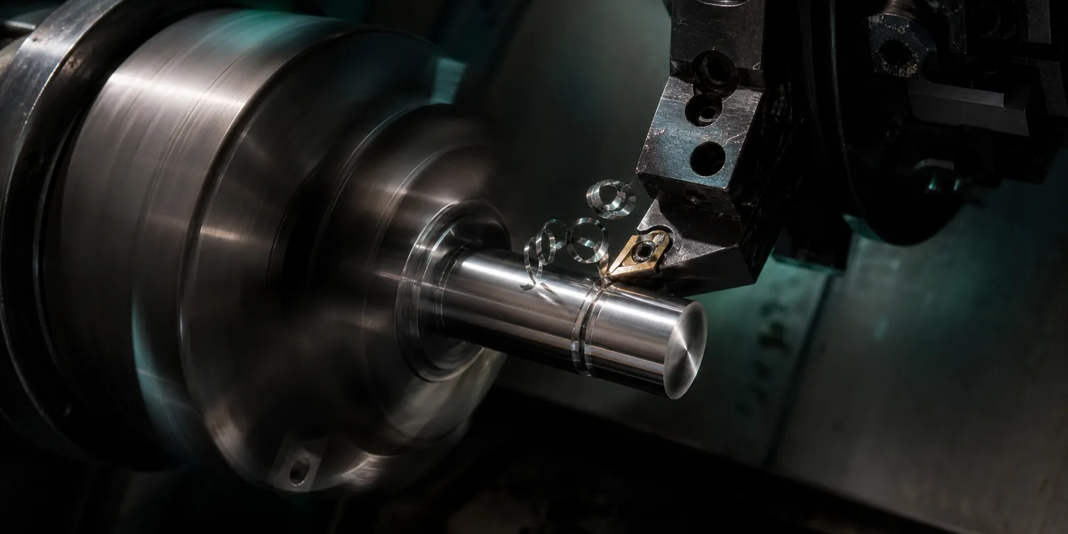
The most fundamental difference between a CNC lathe (turning) and a mill (milling) is "what rotates." In turning, the workpiece is clamped in the spindle and spins at high speed while the tool stays relatively still, feeding along the axial and radial directions to cut the material away ring by ring; milling is the opposite—the tool rotates while the workpiece stays relatively fixed and moves on the table. This difference in "the source of the primary motion" determines the geometry each process is good at (Kalpakjian & Schmid, 2020)[1].
Because the workpiece itself rotates, turning is naturally suited to rotational (axisymmetric) parts—that is, any shape that can be described by revolving around a single center axis: outer diameters, bores, tapers, faces, undercuts, and threads. Milling suits prismatic parts—squared-off parts dominated by planes, pockets, slots, and contours. When classifying machining features, manufacturing-engineering textbooks use exactly "rotational vs prismatic" as the first-level criterion for choosing turning or milling[1]. Remember this line and you can classify eight out of ten parts at a glance.
02Which parts belong on a lathe?
As long as the body of a part is "a shape generated by a rotating axis," the lathe is usually the most efficient choice. Common turned parts include:
- Shafts: drive shafts, spindles, stepped shafts, lead screws—outer diameters, steps, and threads are formed in a single turning operation, with naturally good concentricity.
- Sleeves and bushings: tubular parts needing concentric inner and outer diameters; the lathe turns the OD and bores the ID in the same setup, making concentricity easiest to guarantee.
- Flanges and discs: circular plates dominated by a face, outer diameter, and center hole, where turning gives high face flatness.
- Nuts, fittings, nozzles: small rotational bodies with internal and external threads and tapers.
The knack for judging is: imagine the part spinning on the lathe—if most features can be completed by feeding the tool along the axial and radial directions, it belongs on the lathe. Conversely, if the part has many cross-holes, keyways, planes, or asymmetric contours, these features that "break the rotational symmetry" need milling—which brings us to mill-turn.
03The value and cost of mill-turn machines
Many real parts are neither purely turned nor purely milled, but "a rotational body carrying non-rotational features": for example, a shaft that, after its OD is turned, still needs a cross oil hole drilled in the side, a keyway milled, and a tapped hole on the face. The traditional approach is to turn it on the lathe first, then move it to the mill for a second setup. Every re-setup and re-location introduces new positioning error and lengthens the waiting and handling between machines.
The core value of a mill-turn (multitasking) machine is exactly integrating turning and milling into the same machine, completed in a single setup. The classic literature on automation and computer-integrated manufacturing notes that reducing repeated setups and handling of the workpiece during the process is precisely the key means of lowering accumulated error, shortening flow time, and reducing work-in-progress inventory (Groover, 2019)[2]. When turning and milling are completed under the same datum in one go, the position tolerance of a cross-hole to the OD and the symmetry of a keyway to the axis are both easier to achieve reliably.
But a mill-turn machine is not a cure-all, and its cost has to be counted too: higher machine price and maintenance, more complex program and fixture planning, and operators who need to understand both turning and milling. Using common industry situations as an example, when it's worth investing can be judged from a few angles:
| Situation | Preferred approach |
|---|---|
| Pure rotational body, no cross features | A conventional CNC lathe suffices, most economical |
| Pure plates, housings, mold inserts | Milling (3-axis / multi-axis) as the main method |
| Rotational body + cross-holes / keyways / face milling, with high concentricity and position-tolerance requirements | Single mill-turn setup, benefiting both accuracy and lead time |
| Multiple setups needed, batch has scale, frequent machine-to-machine handling | A mill-turn machine is often more economical after amortization |
In other words, a mill-turn machine trades "higher machine cost" for "lower setup error and flow time." Whether that trade pays off depends on the part's accuracy requirements and batch size, not on blindly chasing equipment tier.
04The chatter and rigidity limits of turning
Although turning is efficient for rotational bodies, it has one unavoidable physical limit: rigidity and vibration. The authoritative text on metal-cutting mechanics and machine-tool vibration notes that if the workpiece-tool system lacks rigidity during cutting, regenerative chatter is prone to occur at certain speeds and depths of cut, worsening tool marks, destabilizing dimensions, reducing tool life, and in severe cases breaking the tool (Altintas, 2012)[3].
The most typical rigidity challenge in turning is the slender shaft: the farther the workpiece extends from the chuck and the smaller its diameter, the softer the cantilever and the more prone it is to deflection and vibration under radial cutting force. Common countermeasures on the floor include shortening the workpiece overhang, adding support with a tailstock center or a steady rest, reducing depth of cut and feed, and adjusting speed to avoid the system's resonance band[3]. These trade-offs involve the current workpiece condition, tool wear, and clamping rigidity, and belong to on-the-spot floor practice that is hard to settle once and for all with one fixed set of parameters.
Further reading: chatter is essentially a trade-off among feed, speed, depth of cut, and system rigidity. For how cutting parameters balance rigidity against efficiency, see this blog's Cutting Parameters and AI-Assisted Reading; for the toolpath and cycle formats at the G-code level, see The Complete Introduction to G-code.
05How to classify turned, milled, and mill-turn parts when sourcing
For the purchasing or design side, classifying parts yourself before sourcing makes quoting faster and easier to align with the supplier. You can judge in this order:
- First check whether the body is rotational: can it be described as "generated by a rotating axis"? If so, think of turning as the main axis.
- Then find the features that break symmetry: are there cross-holes, keyways, planes, or asymmetric contours? If so, milling needs to step in.
- Evaluate the relationship of these features to the turned surfaces: if the cross features have high position-tolerance or concentricity requirements relative to the turning datum, completing them in a single setup (mill-turn) significantly reduces risk; if the requirements are loose, machining across two machines is also viable and more economical.
- Mark datums and tolerances clearly: clearly indicate the center-axis datum and the key concentricity and position tolerances, so the supplier can correctly choose the process and clamping and won't quote high just to be conservative.
A clear drawing and datums are often more important than specifying a machine—letting the supplier choose the most suitable process by the part's characteristics is usually more economical than the buyer overstepping to dictate the equipment.
06AI drawing reading for rotational parts: what it can and can't do
Rotational parts have a highly structured way of being expressed on a 2D drawing: outer diameters, bores, steps, undercuts, threads, and tapers are usually marked with standard dimensions and symbols. This kind of structured feature is exactly where AI drawing reading is more capable.
What AI can do: recognize rotational profiles and features such as OD, bore, thread, and undercut from native electronic drawing files like DWG, make an early call on whether it's a pure turned part, a pure milled part, or "a rotational body + cross features" that should consider mill-turn, and thereby speed up quoting and process drafting; it can also, after modeling, have a second independent AI cross-check the 3D-model dimensions against the original drawing and proactively flag anomalies.
What AI doesn't do: whether a slender part needs a steady rest, the clamping and flip strategy, how to set the concentricity datum, how to adjust the speed to avoid chatter—these decisions involving on-floor machine condition and mechanical judgment, along with the final sign-off before running, still rest with an experienced machinist. AI is responsible for reading, recognizing, and drafting, while the process decision and final confirmation stay with people; this human-in-the-loop line does not disappear just because the part is rotational. If you want to first understand the overall positioning, see What Is AI CNC.
07FAQ
How do I quickly tell whether a part belongs on a lathe or a mill?
Start with the basic shape. If the body is a rotational form generated by revolving around a center axis (shafts, sleeves, flanges, nuts, nozzles), most features can be formed in a single turning operation, so favor the lathe; if it's a squared-off plate, housing, or mold insert, or a prismatic shape dominated by planes, pockets, and slots, favor the mill. When a rotational body also carries cross-holes, keyways, or face milling, that is exactly where mill-turn shines.
Mill-turn machines are more expensive—when is it worth using one?
The core value is "completing turning and milling in a single setup," reducing the accumulated error of repeated repositioning and shortening machine-to-machine handling. When concentricity and position tolerances are demanding, or when multiple setups are needed and the batch has scale, a mill-turn machine improves accuracy and lead time at the same time and is usually more economical. For a simple rotational body or a simple plate part, a conventional lathe or mill is actually more economical.
Why does turning a long, slender shaft vibrate and give a poor surface?
Vibration in turning is directly related to rigidity. The farther the workpiece extends from the chuck and the smaller its diameter, the lower the rigidity and the more prone it is to chatter under cutting force, causing tool marks, unstable dimensions, and even a broken tool. Countermeasures include shortening the overhang, using a tailstock or steady rest for support, reducing depth of cut, and adjusting speed to avoid the resonance band. This is a mechanical characteristic of the workpiece-tool system and needs on-the-spot judgment on the floor.
Can AI automatically recognize rotational parts and help decide whether to use mill-turn?
AI can recognize structured features from a 2D drawing—rotational profiles, outer diameters, bores, undercuts, and threads—and help make an early call on whether it's a turned part, a milled part, or one that needs mill-turn, speeding up quoting and process drafting. But the clamping strategy, support for slender parts, the concentricity datum, and the final check before running still need an experienced machinist's judgment. AI reads the drawing and drafts, while the process decision and final sign-off stay with people.
Get notified when new articles and video guides go live—no inbox flooding, unsubscribe in one click.
READY FOR A CONTROLLED PILOT?
Take one rotational-part drawing and let AI read it first
From drawing recognition and turned/milled/mill-turn assessment to integrating your shop's tool library, we help define a deployment approach that fits your shop.
Contact a deployment consultant Training courses08References
- Kalpakjian, S., & Schmid, S. R. (2020). Manufacturing Engineering and Technology (8th ed.). Pearson.
- Groover, M. P. (2019). Automation, Production Systems, and Computer-Integrated Manufacturing (5th ed.). Pearson.
- Altintas, Y. (2012). Manufacturing Automation: Metal Cutting Mechanics, Machine Tool Vibrations, and CNC Design (2nd ed.). Cambridge University Press.