CUTTING PARAMETERS & AI
How to Choose Cutting Parameters? The Theory Behind Speed, Feed and Depth of Cut — Plus AI Assistance
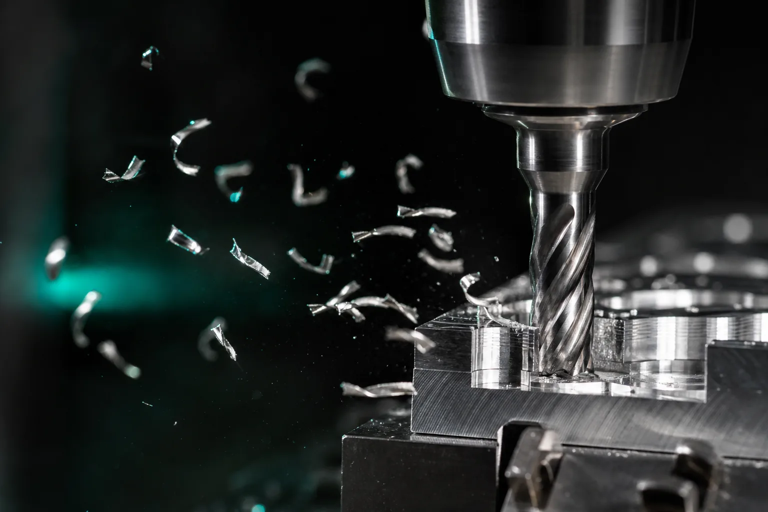
01Cutting parameters are really three variables: speed, feed, depth of cut
Cutting parameters are the settings that decide "how fast, how deep, and how quickly to feed" for a given operation. At the core are three variables that push and pull on one another: cutting speed (usually converted into spindle speed), feed, and depth of cut. What most beginners want is "a formula that directly gives me speed and feed," but in practice only the conversions can be computed cleanly; the parameter "values themselves" depend on the material and shop-floor conditions.
Classic manufacturing-engineering texts treat these three as the main factors governing cutting force, cutting temperature, tool life and surface roughness, and adjusting any one of them ripples through the others[2]. In other words, choosing parameters is not looking up a table and filling in numbers—it is finding the balance among "machining efficiency," "tool life," "surface quality" and "machine stability." That is exactly why the same part can call for different reasonable parameters when you change the machine or the tool.
02Cutting speed and spindle speed: what you can calculate and what you can't generalize
First the calculable part. Spindle speed is derived from cutting speed and tool diameter—cutting speed is the linear speed of the cutting edge relative to the workpiece surface, and the smaller the diameter, the higher the spindle speed needed to reach the same cutting speed. Feed rate is the product of feed per tooth, flute count and spindle speed. Both conversions are deterministic, and they are what the CAM system and controller are constantly computing internally.
What truly can't be generalized is "what cutting speed to use." The choice of cutting speed is directly tied to the machinability of the workpiece material, the tool substrate and coating, and the cutting temperature the pair can withstand; a high cutting speed accelerates flank wear and raises edge temperature, shortening tool life—a trade-off that metal-cutting mechanics and manufacturing textbooks stress repeatedly[2]. So the industry practice is to start from the tool maker's recommended cutting-speed range and the standard parameters accumulated in your shop, rather than applying one universal formula.
03Feed and depth of cut: the surface-quality vs. cutting-force trade-off
Feed and depth of cut determine "how much material you remove at once," i.e. the main source of the material-removal rate, but each has its price:
- Feed (feed per tooth): the larger the feed, the higher the per-tooth load and cutting force, and surface roughness usually worsens too. Finishing favors a smaller feed for a better surface, while roughing increases feed—within the limits the tool and machine allow—to improve efficiency.
- Depth of cut: the deeper the cut, the higher the cutting force and the load on the tool and spindle. How you split radial and axial depth of cut also affects the direction of the load on the tool and its tendency to vibrate—it is not simply "deeper is more efficient."
Authoritative texts on metal-cutting mechanics note that feed and depth of cut mainly determine the chip cross-sectional area and hence the magnitude of the cutting force; excessive cutting force affects not only dimensional accuracy and surface finish but also raises the risk of vibration and tool breakage[1]. So feed, depth of cut and spindle speed must be considered together: at a given material-removal rate the three are an interchangeable combination, and the goal is to complete the job with tool life, surface requirements and stability all acceptable—not to push any one parameter to its maximum on its own.
The relationship among depth of cut, tool length and tool overhang also connects to crash prevention and tool setup—for that, see this blog's Getting started with tool library management and Crash prevention.
04Why does chatter happen? Parameters and system stability
The thing most easily overlooked when choosing parameters—yet most decisive of success or failure—is chatter. Chatter is a self-excited vibration of the entire tool–workpiece–machine system: once triggered, it leaves chatter marks on the workpiece surface and accelerates tool wear, and in severe cases causes dimensional error or a broken tool. The key is that it is not as simple as "the lower the speed, the safer."
Metal-cutting mechanics research uses stability analysis (the concept of the stability lobe diagram) to explain that the system is stable at certain speed/depth combinations while others fall into the unstable region and chatter; with an appropriate choice of speed, you may actually achieve a larger stable depth of cut at a higher spindle speed[1]. This is precisely why the usable parameters for the same tool differ across machines of different rigidity—the stable region depends on the dynamic characteristics of the machine and the fixturing, not just on the tool and material.
The practical meaning for the floor is that choosing parameters can't be about maximizing the material-removal rate alone; you also have to avoid the regions that excite vibration. When chatter marks or unusual noise appear, adjusting the speed (rather than only slowing it down), reducing tool overhang and increasing clamping rigidity are often more effective than simply slowing the feed.
05Parameters aren't set once and done: tool wear and in-process monitoring
Even if you land on a good set of parameters at the start, it is not permanently valid. Tools accumulate wear as machining proceeds, and wear changes cutting force, cutting temperature and surface quality, gradually driving the once-suitable parameters away from their optimum. So "choosing parameters" is really a process that needs feedback and correction.
A CIRP (International Academy for Production Engineering) review of machining monitoring notes that tool condition and machining stability can be monitored through signals such as cutting force, vibration, acoustic emission and spindle power, to detect tool wear, breakage and chatter and feed back adjustments[3]. Most small and mid-sized job shops don't necessarily need an expensive in-process monitoring system, but they can hold to its spirit:
- Record validated parameters together with their tool, material and machine to build a standard parameter table you can accumulate over time;
- Establish simple rules for tool changes and tool life to avoid pushing a tool past its life;
- Treat floor signs like "chatter marks, unusual noise, dimensional drift" as signals that parameters need correcting, and go back and update the standard parameter table.
This "parameters—result—feedback" loop is the key to gradually turning a veteran's feel into an asset the shop can inherit.
06How AI assists parameter selection—bounded by your shop's standard tables
Once you understand the trade-offs above, AI's proper role in cutting parameters becomes clear: it is an accelerator, not a black box that generates parameters out of thin air. Reliable AI assistance should use your shop's existing data as boundary conditions rather than letting the model improvise freely:
| Shop boundary condition | Role when AI assists parameter selection |
|---|---|
| Tool library (code, diameter, flute count, recommended parameters) | Start from tools that actually exist and their recommended cutting speed and feed per tooth to convert reasonable spindle speed and feed |
| Standard parameter table (material × tool × machine) | Treat validated combinations as boundaries; AI drafts within that range, avoiding values divorced from reality |
| Machine speed and travel limits | Check at generation time so it never produces parameters beyond the machine's capability |
| Cutting simulation | After drafting parameters, check travel, interference and collisions in simulation first, reducing trial cuts from scratch |
In other words, AI quickly gives a reasonable starting point within the box of "shop standard parameter table + tool library + machine limits," and screens out obvious travel and collision problems in simulation first; the day's tool condition, clamping rigidity, batch-to-batch material differences and any tendency to chatter are still confirmed and fine-tuned by a senior technician before the job runs. This is consistent with the human-in-the-loop spirit of the overall machining-prep workflow—see the pillar article The complete guide to CNC automated programming. This division of labor lets AI take on the repetitive conversions and preliminary checks while keeping the technician's judgment where it matters most: the final gate.
07FAQ
Is there a standard formula that directly gives me spindle speed and feed?
There are basic conversions: spindle speed is determined by cutting speed and tool diameter, and feed rate is the product of feed per tooth, flute count and spindle speed. But there is no single formula for "what cutting speed and feed per tooth to use"—these vary with workpiece material, tool substrate and coating, tool overhang, machine rigidity and coolant method. The right approach is to start from the tool maker's recommended values and your shop's standard parameter tables, then fine-tune.
Does higher speed and faster feed always mean faster machining?
Not necessarily. Excessive cutting speed accelerates tool wear and heat and shortens life; excessive feed and depth of cut raise cutting forces and can trigger chatter, dimensional error, or even a broken tool. Real efficiency is a trade-off among speed, feed and depth of cut against tool life, surface quality and machine stability—not pushing one parameter to its maximum.
Why does chatter happen, and how is it related to cutting parameters?
Chatter is a self-excited vibration of the tool–workpiece–machine system, closely tied to depth of cut, spindle speed and system rigidity. Metal-cutting mechanics uses stability analysis to describe how certain speed/depth combinations fall in an unstable region and chatter while others stay stable. So parameters must avoid regions that excite vibration, which is why the usable parameters for the same tool differ from machine to machine.
Can AI decide cutting parameters for me?
It works well as an assistant. AI can use your shop's tool library, standard parameter tables and machine speed/travel limits as boundary conditions to draft a reasonable set of parameters and check travel and collisions in cutting simulation, reducing trial cuts from scratch. But before the job runs, a senior technician still needs to confirm based on the day's tool condition, clamping rigidity and workpiece state—AI does not replace the final judgment.
Get notified when new articles and video reviews go live—no inbox flooding, one-click unsubscribe.
READY FOR A CONTROLLED PILOT?
Turn your standard parameter table into the boundary conditions for AI parameter selection
From the tool library and standard parameter tables to machine speed/travel limits, we help connect your shop's existing machining knowledge into AI's prep workflow, so parameter drafting and simulation checks stay closer to the floor.
Contact an implementation advisor Training courses08References
- Altintas, Y. (2012). Manufacturing Automation: Metal Cutting Mechanics, Machine Tool Vibrations, and CNC Design (2nd ed.). Cambridge University Press.
- Kalpakjian, S., & Schmid, S. R. (2020). Manufacturing Engineering and Technology (8th ed.). Pearson.
- Teti, R., Jemielniak, K., O'Donnell, G., & Dornfeld, D. (2010). Advanced monitoring of machining operations. CIRP Annals, 59(2), 717–739.