CNC MACHINING 101
What Is CNC Machining? A Complete Introduction from Mills and Lathes to AI Programming
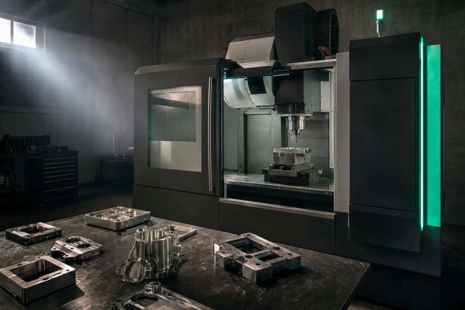
01What is CNC machining? A one-sentence definition
CNC machining (Computer Numerical Control machining) is a manufacturing method in which a computer program controls a machine tool, automatically moving the cutter and workpiece according to pre-written numerical instructions to progressively cut a finished part from a block of metal, plastic or other material. It belongs to "subtractive manufacturing"—forming by removing excess material—the opposite of the "additive manufacturing" of 3D printing that builds material up.
The core of CNC is breaking the machining motions down into a series of coordinates and parameters: which X/Y/Z position the cutter should move to, how fast to feed, what spindle speed to run, which tool to change to. Once these instructions are written into a program and handed to the machine's controller (such as FANUC, Mitsubishi or Heidenhain), the machine can reproduce the same set of dimensions consistently. Classic manufacturing-engineering texts note that CNC can reconcile precision and productivity precisely because it digitizes the "machining information," letting the same program be reproduced, modified and audited (Kalpakjian & Schmid, 2020)[1].
02CNC machine-tool overview: mills, lathes, drills and 5-axis
Although they are all called CNC, different machine tools are good at very different work. The key to telling them apart is usually "what is rotating" and "how many axes of motion there are."
| Machine type | Working principle | Parts it excels at |
|---|---|---|
| CNC mill / machining center | The cutter rotates; the workpiece is fixed on a table that moves along X/Y/Z | Plates, mold cavities, grooves, complex contours and surfaces |
| CNC lathe | The workpiece rotates; the cutter feeds and cuts | Rotationally symmetric parts such as shafts, sleeves and discs |
| CNC drill / tapping | The spindle drives the drill to feed along the axis | Hole machining, drilling, reaming, tapping |
| 5-axis machining center | Two rotary axes added on top of the three linear axes | Multi-face complex parts such as impellers, molds and aerospace structures |
5-axis machining is a recent focus. The two extra rotary axes let the cutter tilt to different angles and machine several faces in a single setup, reducing the accumulated error of repeated repositioning and making shapes that were traditionally hard to machine—such as deep cavities and inclined faces—feasible. But the more axes there are, the higher the chance of collision between the cutter, workpiece and fixtures, so path planning and simulation become all the more critical—authoritative texts on metal-cutting mechanics and CNC design stress that tool paths must be based on the mechanics and vibration characteristics of the tool–workpiece system, or you get tool marks and poor accuracy at best, and a broken tool or crash at worst (Altintas, 2012)[3].
03CNC machining vs. traditional manual machining
Traditional manual machining has a machinist turn handwheels to operate the machine, and the accuracy and consistency of the part depend on the person's feel and experience; CNC controls axis motion automatically with a program. The difference between the two can be summed up in three points:
- Repeatability: in manual machining every part depends on a person re-touching-off and feeding, so there is inevitable variation from part to part; with CNC, as long as the program and tools stay the same, part No. 1 and part No. 500 are almost identical in dimension.
- Complexity: complex surfaces, precise hole positions and multi-face machining are almost impossible to reproduce consistently by hand, whereas CNC can run through them precisely by program.
- Labor pattern: CNC supports long, even unattended operation, and one person can tend several machines at once.
It is worth noting that CNC has not made "experience" unimportant—it has moved it forward. Research on automation and computer-integrated manufacturing repeatedly notes that after adopting numerical control, the deciding point of quality shifts from "operating on the floor" to "process planning and program verification before machining" (Groover, 2019)[2]. In other words, the machinist's skill has moved from "the hands" into "the program."
04The complete machining flow: drawing → programming → machine → inspection
A CNC-machined part usually goes through four stages from quote to shipment:
- Drawing and quotation: the customer provides a 2D engineering drawing (DWG, PDF) or a 3D model, specifying dimensions, tolerances, material and surface-treatment requirements. This step is also the starting point of estimating—the more complete the drawing, the more accurate the quote (further reading: CNC RFQ and quotation guide).
- Process planning and programming: the engineer rebuilds or confirms the 3D model from the drawing, decides the fixturing, cutting sequence and tools, and then generates tool paths with CAM software and outputs the G-code.
- Machining on the machine: the program and tool settings are loaded into the machine, and after tool touch-off, setting the workpiece coordinates and a test cut, formal machining begins.
- Inspection and delivery: dimensions and tolerances are compared with gauges, a CMM or a projector. Dimensions without individually indicated tolerances are generally judged by the ISO 2768 general tolerances[5]; before volume production a first article inspection (FAI) is usually done first to confirm the process is correct.
Across the whole flow, stages 1 and 2 (reading the drawing, modeling, programming) consume the most time and experience and are often the bottleneck for lead time and quality—and are exactly where AI first steps in.
05G-code: the common language of CNC machines
Whichever CAM software you use, what finally goes into the machine is almost always G-code—the numerical-control program format specified by ISO 6983, which uses G commands (motion and cycles), M commands (machine actions), plus coordinate and feed parameters to describe, line by line, how the cutter should move[4]. In use since the 1950s, it is the de facto common language of the CNC world.
But G-code only describes "tool motion"; it does not retain design intent or process information, and with dialect differences between controllers, the same program often cannot run directly across different machines. This is why "loading a G-code and running it straight on the machine" carries risk—it must correspond to the correct machine, tools and clamping conditions. For a deeper look at the command structure and automatic generation, see The complete G-code primer.
06Common machining materials and applications
CNC can machine almost any cuttable material, but each material's "machinability" differs, affecting tool choice, cutting parameters and cost:
- Aluminum alloys: light, with good machinability and heat dissipation—a regular for prototyping and electronic and mechanical parts.
- Carbon steel / stainless steel: high strength and wide application; stainless work-hardens markedly and demands more of tools and cooling.
- Titanium and superalloys: excellent strength-to-weight ratio but poor thermal conductivity and prone to galling—difficult-to-machine materials common in medical devices and aerospace.
- Engineering plastics (POM, PEEK, etc.): used for insulating, wear-resistant and lightweight parts.
A material's mechanical and thermal properties directly determine the difficulty and quality of machining, and are conditions that must be clarified first during process planning (Kalpakjian & Schmid, 2020)[1]. In terms of application, CNC machining broadly underpins the production of semiconductor equipment, molds, medical devices, aerospace, automotive and all kinds of precision mechanical parts.
07How AI is changing CNC machining
Back to the flow's bottleneck: reading drawings, modeling and programming are time-consuming and highly dependent on a few veterans. This is exactly where AI can shine. A new generation of AI-assisted programming (AI CAM) can automatically recognize a 2D drawing as machining features and generate a 3D model, draft G-code based on the shop's tool library and machine limits, and then use 3D cutting simulation and independent AI dimensional cross-checking to catch anomalies before the job runs. This aligns with the long-standing goal of computer-integrated manufacturing: to let design information convert smoothly into manufacturing instructions and reduce the errors and waiting of manual translation (Groover, 2019)[2].
But it must be stressed that AI does not replace the machinist but divides the labor: AI speeds up prep, while tolerance interpretation, datum setting, special methods and the final confirmation before the job runs remain in the hands of professionals—the human-in-the-loop model; confidential drawings under NDA can be handled with a fully offline on-premise deployment (on our roadmap). For the full picture of this approach, see What is AI CNC.
08FAQ
What is CNC machining?
CNC machining (computer numerical control machining) is a manufacturing method in which a computer program controls a machine tool, automatically moving the cutter and workpiece by numerical instructions to progressively cut a finished part from a block of material. It lets the program decide the path, feed and spindle speed, reproducing the same set of dimensions consistently—suited to precision parts and volume production.
What is the difference between a CNC mill and a lathe?
The difference is what rotates. On a lathe, the workpiece rotates and the cutter feeds, suited to rotationally symmetric parts such as shafts; on a mill, the cutter rotates and the workpiece moves on a table, suited to plates, mold cavities and complex contours. A 5-axis machining center adds two more rotary axes, so it can machine several faces in one setup.
How does CNC machining differ from traditional manual machining?
Manual machining relies on a machinist operating handwheels, with accuracy depending on feel and experience; CNC controls axis motion automatically with a program, giving high repeatability, complex-surface capability and long unattended operation. With CNC, the center of gravity of quality moves forward from operating on the floor to reading the drawing, planning the process and verifying the program before machining.
Will AI replace CNC machinists?
It won't replace them, but divide the labor. AI is suited to automating time-consuming prep, such as reading drawings and modeling, preliminary tool planning, drafting G-code and cross-checking dimensions before machining; tolerances, datums, special methods and the final confirmation before the job runs still need a senior machinist's oversight.
Get notified when new articles and video reviews go live—no inbox flooding, one-click unsubscribe.
FROM DRAWING TO VERIFIED G-CODE
Want to see how AI turns a drawing into a verifiable machining program?
Whether you want to understand adopting CNC or already have a drawing to try, we help define the approach that fits your shop.
Contact an implementation advisor Training courses09References
- Kalpakjian, S., & Schmid, S. R. (2020). Manufacturing Engineering and Technology (8th ed.). Pearson.
- Groover, M. P. (2019). Automation, Production Systems, and Computer-Integrated Manufacturing (5th ed.). Pearson.
- Altintas, Y. (2012). Manufacturing Automation: Metal Cutting Mechanics, Machine Tool Vibrations, and CNC Design (2nd ed.). Cambridge University Press.
- ISO 6983-1:2009. Automation systems and integration — Numerical control of machines — Program format and definitions of address words. International Organization for Standardization.
- ISO 2768-1:1989. General tolerances — Tolerances for linear and angular dimensions without individual tolerance indications. International Organization for Standardization.