MATERIALS & MACHINING
Aluminum Machining 101: Cutting Behavior of 6061 and 7075 and How to Think About CNC Parameters
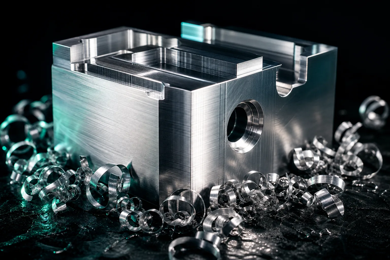
01Why is aluminum the most common material in CNC?
Aluminum machining is the work most frequently encountered on the CNC shop floor in Taiwan, and the reasons come down to several intrinsic material advantages. First, aluminum's machinability is markedly better than that of most steels and stainless steels — low cutting forces, long tool life, and the ability to run high cutting speeds — a conclusion that is fairly consistent across manufacturing-engineering textbooks comparing the machinability of various materials (Kalpakjian & Schmid, 2020)[1]. Second, aluminum's density is only about one-third that of steel, yet through alloying and heat treatment it can achieve quite considerable strength, letting it satisfy both lightweighting and structural requirements at once.
Add to this that aluminum alloys are easy to anodize for corrosion resistance and appearance, and they are widely used in consumer-electronics housings, heat sinks, fixtures, aerospace, and automation structural parts. For a job shop, this means aluminum parts are not only high in volume and variety but also come with demanding surface and dimensional requirements — mastering the fundamentals of aluminum machining is a prerequisite for taking on high-value orders.
026061 vs 7075: comparing the two workhorse aluminum alloys
Among the many grades, 6061 and 7075 are the two most common on the CNC floor. 6061 belongs to the Al-Mg-Si system (6000 series), with moderate strength and well-balanced overall performance; 7075 belongs to the Al-Zn-Mg-Cu system (7000 series) and is one of the highest-strength wrought aluminum alloys. Here is a qualitative comparison of the properties the shop floor cares about:
| Aspect | 6061 (6000 series) | 7075 (7000 series) |
|---|---|---|
| Alloy system | Al-Mg-Si | Al-Zn-Mg-Cu |
| Strength level | Moderate (commonly in the T6 temper) | High; some properties approach mild-steel grades |
| Hardness | Moderate | Noticeably higher |
| Ductility / toughness | Better | Lower; more sensitive to notches and cracking |
| Corrosion resistance | Good | Poorer (often reinforced with alclad or surface treatment) |
| Machinability | Excellent; chip form easy to control | Excellent, but higher tool load due to greater hardness |
| Typical uses | General structures, housings, fixtures, heat sinks | Aerospace, high-load structures, molds |
Note: The table above is a qualitative comparison of mechanical properties; actual values should follow the material supplier's spec sheet and temper (e.g., T6, T651). Machining parameters are not listed here — always defer to the in-house standard parameter table.
From a machining standpoint, both have excellent machinability, but the difference is this: 7075 has higher hardness and strength, so the tool bears greater cutting forces and thermal load, and its lower ductility makes it more prone to cracking or chipping at thin walls, sharp corners, and stress concentrations; 6061 is more forgiving, with better-controlled chip form, making it the first choice for entry-level and general-purpose parts. Material selection should be driven by the part's strength, corrosion, and post-processing requirements — ease of machining is only one factor in the mix, which is exactly why process planning needs a dialogue with the design side (Chryssolouris, 2006)[3].
03Galling and built-up edge: aluminum's most classic surface killer
Aluminum "cuts easily," but that does not mean it "cuts beautifully." The most classic quality problem in aluminum machining comes from built-up edge (BUE). Aluminum has high chemical affinity and a low melting point, so in the lower cutting-speed range the chip material readily adheres and accumulates at the leading edge of the cutting edge, forming a false cutting tip that continuously builds up and breaks away. Classic metal-cutting mechanics texts note that BUE periodically grows and fractures, carrying material fragments onto the finished surface, directly degrading surface roughness and making dimensions unstable (Altintas, 2012)[2].
The way to combat BUE is to move machining out of the range where it readily forms; common approaches include:
- Sharp, high-rake tools: aluminum-specific end mills typically use large rake angles and polished or highly finished flutes to reduce material adhesion.
- An appropriate cutting speed: raising the cutting speed usually helps clear the low-speed range where BUE is prone to form, but it must stay within the capability of the machine and tool.
- Ample lubrication: cutting fluid or oil mist reduces friction and the tendency to adhere.
- Suitable coated or uncoated aluminum-specific tools: avoid coatings with high affinity for aluminum to reduce cold welding.
These directions are interrelated, and the specific speed and lubrication conditions must still follow the in-house tooling and parameter tables — it is unwise to force-fit a single "number found on the internet."
04Chip evacuation and cooling: why aluminum chips are especially troublesome
Aluminum's high cutting speeds and large metal-removal rates bring another practical problem: a large volume of sticky chips. Aluminum chips are light, tangle easily, and readily pile up in deep slots and pockets; if they cannot be cleared, they get re-cut by the tool, causing a sudden spike in edge load, surface scratching, and, in severe cases, even tool breakage. So in aluminum machining, "getting the chips out" is almost as important as "cutting the material away."
In practice, several angles are addressed: choose aluminum-specific tools with large chip clearance and few flutes (e.g., 2–3) to accommodate large chips; make good use of high-pressure cutting fluid or air blast to blow chips out of the cutting zone; and in deep pockets, use trochoidal or layered strategies to control the engagement angle and avoid burying the full flute. Aluminum conducts heat well, so most of the heat is carried away by the chips, which means the cooling strategy must serve both "cooling down" and "flushing chips" at the same time. Good chip-evacuation and cooling planning is essentially part of process design, requiring the tool, path, and fixtures to be arranged as a single system (Chryssolouris, 2006)[3].
05Thin walls and distortion: the workholding and residual-stress challenge
Aluminum parts are often designed as thin-walled, lightweight structures, which makes "distortion" the core difficulty in high-precision aluminum machining. Distortion has three main sources: cutting force pushing the thin wall away, clamping force crushing the workpiece, and the material's own residual stress releasing after material is removed. Stacked together, these cause measurements to drift as machining progresses, so the final dimensions "wander off."
Common lines of countermeasure include:
- Symmetric, layered material removal: remove material symmetrically layer by layer so residual stress releases as evenly as possible, rather than digging straight to depth in one pass.
- Leave a finishing allowance: after roughing, leave a thin allowance and finish it in a final light pass with a sharp tool to reduce the cutting force pushing on the thin wall.
- Low-stress workholding: use a vacuum chuck or multi-point low-pressure clamping to avoid local clamping forces crushing the part; add auxiliary supports where needed.
- Sequence the machining: complete critical dimensions while the workpiece is still in a more rigid state.
These all belong to the domain of process planning and experienced judgment, requiring combined decisions based on part geometry, material condition, and machine capability — hard to cover with a single rule, which is exactly where a master machinist's experience delivers the most value. If you want to reduce machining difficulty starting from the design side, see our dedicated article on Design for Manufacturability (DFM).
06How to think about cutting parameters: grounded in mechanics, bounded by the in-house table
Beginners most want an "aluminum speed-and-feed table," but that is exactly what to be careful about. The authoritative texts on cutting mechanics and CNC design are clear: the reasonable range for feed, speed, and depth of cut depends on the mechanics and vibration behavior of the tool–workpiece system, including tool material and geometry, machine rigidity and power, and clamping rigidity and cooling conditions; once you step outside the stable range, at best you get tool marks and dimensional defects, and at worst chatter, tool breakage, and a crash (Altintas, 2012)[2]. In other words, the optimal parameters for the same tool differ across machines and setups, and borrowed numbers are not portable.
The more pragmatic approach is to build a "way of thinking" rather than a set of "numbers": first understand that the material must clear the BUE range, that cutting force and heat must be controlled, and that stable cutting engagement must be preserved; then use the in-house standard parameter table as the starting point and boundary for each class of tool-and-material combination; and finally converge by fine-tuning based on the actual surface, sound, and measurements from test cuts. Manufacturing-engineering texts also emphasize that the machining result is a systemic outcome of the interaction between material, tool, parameters, and machine, not something decided by a single variable (Kalpakjian & Schmid, 2020)[1]. Institutionalizing this logic and writing it into the parameter table is what makes machining capability repeatable and transferable. To dig deeper into the relationship between parameters and mechanics, see Cutting Parameters and AI Assistance.
07How AI uses the in-house parameter library to assist aluminum machining
Once you understand the difficulties above, you can see AI's correct role in aluminum machining clearly: it is not there to conjure up a set of magic parameters, but to turn the shop's existing knowledge into constraints that can be applied automatically and verified. In our workflow, for example, after the AI reads the customer's 2D drawing (DWG preferred, PDF or photos as backup), recognizes the machining features, and builds a 3D model, it generates the G-code bounded by the in-house tool library, the controller dialect, the travel and speed limits, and the standard parameter table — selecting tools that actually exist and applying the approved parameter range for that material-and-tool combination, rather than letting the model invent values out of thin air. For the related drawing-reading and code-generation workflow, see The Complete Workflow from 2D Drawings to G-code.
Next, the program first goes through a 3D cutting simulation to check for gouges, remaining stock, and interference, and then a separate AI cross-checks the model dimensions against the original drawing's annotations and proactively flags anomalies, reducing missed checks. The thin-wall distortion, workholding strategy, and final tolerance confirmation that are especially critical for aluminum parts are still gated by on-site professionals — a human-in-the-loop workflow where AI accelerates preparation and the master machinist retains the final judgment is the reliable way to scale aluminum-machining experience. When taking on NDA-covered jobs, the entire workflow can run in a fully offline on-premise environment so drawings never leave the shop.
08FAQ
Which is easier to machine, 6061 or 7075 aluminum?
Both have better machinability than most steels, but 6061 is more balanced: moderate strength, easy to machine, easy to anodize — the most general-purpose choice. 7075 is high-strength and common in aerospace and high-load structures, but it has lower ductility and is more sensitive to machining stress and cracking, so take particular care at thin walls and sharp corners. Material selection should be driven by the part's strength requirements and post-processing; ease of machining is only one of the considerations.
Why does aluminum machining tend to gall and form built-up edge?
Aluminum has high affinity and a low melting point, so in the lower cutting-speed range it readily adheres to the tool, forming a built-up edge (BUE) that periodically builds up and breaks off, degrading the surface and destabilizing dimensions. Countermeasures include sharp, high-rake aluminum-specific tools with polished flutes, together with ample lubrication and an appropriate cutting speed to move machining out of the BUE-prone range. Specific values follow the in-house standard parameter table.
How do you deal with distortion when machining thin-wall aluminum parts?
Distortion comes mainly from cutting force, clamping force, and residual stress. Common countermeasures include removing material symmetrically in layers to balance stress, leaving a finishing allowance for a final light cut, switching to vacuum or multi-point low-pressure clamping to avoid crushing, and sequencing the machining so critical dimensions are completed while the part is still rigid. This is process planning and requires combined judgment based on part geometry and material condition.
What spindle speed and feed should I use for aluminum?
There is no universal number. Reasonable speed, feed, and depth of cut depend on tool material and geometry, machine rigidity and power, and clamping and cooling conditions, and must be grounded in the mechanics and vibration behavior of the tool–workpiece system. In practice, use the in-house standard parameter table as the boundary and fine-tune to actual conditions; an AI-assisted system likewise generates programs constrained by this parameter library rather than letting the model invent values freely.
Get notified when new articles and video guides go live — no inbox flooding, one-click unsubscribe.
READY FOR A CONTROLLED PILOT?
Turn your aluminum-machining experience into repeatable parameters and processes
From the tool library and standard parameter table to thin-wall and NDA requirements, we help define the AI-assisted rollout that fits your shop.
Contact a rollout consultant Training courses09References
- Kalpakjian, S., & Schmid, S. R. (2020). Manufacturing Engineering and Technology (8th ed.). Pearson.
- Altintas, Y. (2012). Manufacturing Automation: Metal Cutting Mechanics, Machine Tool Vibrations, and CNC Design (2nd ed.). Cambridge University Press.
- Chryssolouris, G. (2006). Manufacturing Systems: Theory and Practice (2nd ed.). Springer.