CNC MACHINING · DRILLING
Drilling Isn't as Simple as It Looks: From Center Drilling and Peck Cycles to Deep-Hole Machining
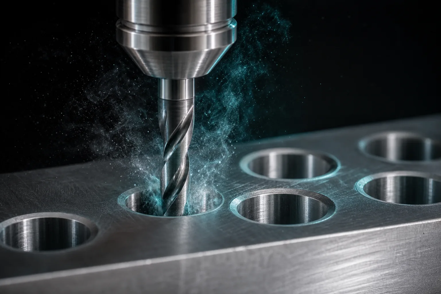
01Why "drilling" isn't actually simple: the two big problems of chip evacuation and wander
Drilling looks like nothing more than pushing a drill down to make a hole, but it has the worst chip-evacuation conditions of any cutting process: cutting happens at the bottom of the hole, and the chips must travel all the way up the drill's helical flutes, against the feed direction, to get out. The deeper the hole, the longer and more crowded that evacuation path becomes. Classic manufacturing-engineering texts note that chip removal, cutting heat and torque control in drilling are the core variables determining hole accuracy, surface quality and tool life (Kalpakjian & Schmid, 2020)[1]. Once chips jam inside the hole, cutting heat can't be carried away, torque spikes sharply, and at best you scratch the wall and lose the diameter—at worst the drill seizes and snaps.
The second problem is positional wander and straightness. The center of an ordinary twist drill is a non-cutting "chisel edge" that tends to skate across the surface at the moment of entry, unable to locate itself, so the entry drifts off target or even bell-mouths; a slender drill lacks rigidity and can wander progressively deeper into the cut. The metal-cutting-mechanics literature reminds us that vibration and tool deflection during cutting are reflected directly in machined accuracy, and the rigidity and stability of the tool–workpiece system must be built into process design (Altintas, 2012)[2]. Chip evacuation and wander are exactly the two problems every technique that follows is meant to solve.
02Center-drill spotting: hole accuracy is decided by the first cut
The first move against wander is to not let the drill "hunt" for the hole position itself. The approach is to first use a rigid, deflection-resistant center drill or spot drill to cut a shallow conical dimple at the target location. That dimple gives the following twist drill a guide: the drill point drops into the dimple, the chisel edge no longer has a chance to skate, and both positional accuracy and the roundness of the entry improve noticeably—straightness is easier to hold, too.
Spotting looks like extra time, but it's a leverage point for accuracy. It's practically mandatory when the hole has a defined positional tolerance, a larger diameter (longer chisel edge, more prone to skating), a high depth-to-diameter ratio, or when the workpiece surface is sloped or curved; conversely, for shallow, low-precision holes, or when using a self-centering drill-point geometry, it can be simplified as circumstances allow.
03G81 and G83: the concepts behind plain drilling and peck cycles
CNC controllers build in "canned cycles" for common hole operations so the programmer doesn't have to write out the plunge, feed and retract line by line for every hole—just call a code, give the hole depth and parameters, and the controller runs the whole motion automatically and repeats it over many hole positions. The format and address-word definitions of these G-codes fall under the ISO 6983 numerical-control program standard[3]. The two most-used concepts in hole work are:
- G81 plain drilling cycle: the drill rapids down to just above the workpiece, feeds straight to the specified depth in one pass, then retracts. Suited to shallow holes with smooth chip flow and a low depth-to-diameter ratio—when chip volume is small, drilling straight to depth is most efficient.
- G83 peck (deep-hole) cycle: the full depth is cut in multiple "pecks." The drill cuts a short distance, then fully retracts out of the hole to fling off chips and let coolant reach the bottom, then returns to the previous depth to continue. It repeats in steps until depth is reached. Its core value is forcing chip breaking and evacuation.
The difference between the two is essentially a "chip-evacuation strategy." Shallow holes have short chips that escape, so use G81; deep holes have long chips that tangle and clog, so you must use G83 and clear chips by repeated retraction. Some controllers also offer a "high-speed peck" variant that retracts only a short distance to break chips without fully withdrawing, suited to medium-depth holes where efficiency comes first—but for deep holes, full retraction is still the safer choice to thoroughly clear chips and cool. For a fuller picture of G-code and canned cycles, see this blog's complete introduction to G-code.
04The challenges of deep-hole drilling: chip breaking, cooling and straightness
As the depth-to-diameter ratio (hole depth ÷ hole diameter) grows, drilling upgrades from a "routine operation" to deep-hole drilling, which needs dedicated treatment. Difficulty doesn't rise linearly—three problems worsen at once:
- Chip breaking and evacuation: the deeper the hole, the longer the path chips must climb. If chips can't reliably break into short pieces, long stringy chips wrap around the flutes and form a "chip plug," instantly spiking torque and breaking the drill. This is the most common failure mode in deep holes, and the reason the G83 peck cycle exists.
- Cooling and lubrication: cutting heat concentrates at the hole bottom—the very place coolant reaches least easily. Heat that can't be carried away accelerates tool wear and throws off the diameter through thermal expansion. Deep holes often need a stronger retract-and-clear rhythm, and where rigidity allows, through-tool coolant (delivering coolant straight to the cutting point via internal tool channels).
- Hole straightness (wander): a slender drill has low rigidity and, as the hole deepens, tends to drift off axis under cutting force and material inhomogeneity, with deviation accumulating more noticeably the deeper it goes. Good center-drill spotting, steady feed, and where necessary a more rigid dedicated deep-hole tool are all means of controlling straightness. The stability and vibration control of the cutting process directly determine whether a deep hole can hold accuracy (Altintas, 2012)[2].
In other words, every deep-hole challenge comes back to the same thing: let chips leave smoothly, let heat carry away, and keep the drill running straight. The larger the depth-to-diameter ratio, the more you need to plan retract rhythm, feed and tool choice together at the programming stage.
05Hole post-processing: reaming, boring and tapping
A crucial but often-overlooked point: drilling itself is roughing. The hole a twist drill makes has limited diameter tolerance and roundness, and the surface isn't smooth enough. When the drawing demands more of a hole, drilling must be followed by different finishing operations (Kalpakjian & Schmid, 2020)[1]:
- Reaming: using a reamer to lightly finish an already-drilled hole, mainly to improve diameter accuracy and surface roughness. An appropriate reaming allowance must be left beforehand—too much or too little won't produce a good hole.
- Boring: finishing the hole with a single-point boring tool, giving precise control over diameter size, roundness and positional/concentric accuracy, suited to large diameters or holes with tight positional requirements—things reaming can't do.
- Tapping / thread machining: when a hole needs an internal thread, drill the correct pilot hole first, then tap; thread depth, chip evacuation and lubrication all need attention. For large diameters or special materials, thread milling is an alternative. For details on chip breaking and pilot-hole planning in tapping, see this blog's guide to tapping and thread machining.
For designers, the key is to think about downstream operations when you dimension the hole: a hole that needs both a precision fit and a thread requires the shop to plan the full tool sequence "spot → drill pilot → ream/bore → tap" and to leave allowance. Spell out the hole's tolerance and method clearly, and quotes and lead times will be accurate—and you avoid discovering on the machine that the target can't be met.
06The role and limits of AI in hole-feature recognition and cycle generation
Hole work is one of the operations best suited to AI assistance, because a hole is a highly standardized, structurally describable feature. In practice AI can recognize hole features from a drawing (position, diameter, depth, whether it's a threaded hole), automatically compile a hole table, and draft spotting and drilling cycles for standard hole positions—greatly speeding up the tedious per-hole setup of the past. This requires feeding in the shop's tool-library drills, reamers and taps so AI selects tools that actually exist; see this blog's article on tool-library management.
But the honest limits are just as clear—the following judgments still need engineer confirmation for now:
- Through vs. blind holes: when drawing information is incomplete or input as a photo, AI can misjudge whether a hole passes through, directly affecting hole depth and retract strategy.
- Whether a deep hole gets a peck cycle and how the retract rhythm is set: the depth-to-diameter ratio and material decide whether to use G83 and how deep each peck goes, which involves shop-floor chip-evacuation experience.
- Method choice for tolerance holes: whether to ream, bore, or just drill depends on tolerance and fit intent, and must be an engineer's call.
So the right framing is "AI speeds up hole programming; the machinist keeps the final call on method and safety." AI-generated drilling cycles should still be run through cutting simulation and a senior technician's review—confirming tool length, retract and travel safety—before going on the machine, consistent with the human-in-the-loop principle of AI CAM as a whole. See the pillar article, the complete guide to CNC auto-programming.
07FAQ
Why does deep-hole drilling have to use a peck cycle (G83) instead of drilling straight to depth?
The deeper the hole, the harder chips are to evacuate. Drilling straight to depth packs chips between the flutes and the hole wall, causing poor evacuation, heat buildup and a sudden torque spike—at best an out-of-spec diameter, at worst a broken, seized drill. G83 drills a short distance, then retracts out of the hole to break and clear chips before feeding back in, snapping long chips and carrying heat away—the key to whether deep-hole drilling stays stable.
Is a center drill (spot drill) necessary, or can it be skipped?
On high-precision or high depth-to-diameter holes, skipping it is not advised. A twist drill's chisel edge tends to skate at the moment of entry, causing wander and a bell-mouthed entry. Starting with a rigid center drill to cut a shallow dimple gives the following drill a guide, improving both position and straightness. For shallow, low-precision holes or when using a self-centering drill point, it can be simplified as circumstances allow.
For a hole to meet tolerance and surface requirements, is drilling alone enough?
Usually not. Drilling is roughing, with limited diameter tolerance and roundness. For precise size, ream to finish the diameter and surface; for tight concentricity and positional accuracy, bore; for threads, tap or thread-mill. When a designer dimensions a hole, they should account for downstream operations so the shop can plan the correct tool sequence and stock allowance.
Can AI automatically read holes off a drawing and generate drilling cycles?
For standard hole positions and regular diameters, AI can recognize hole features, compile a hole table and draft spotting and drilling cycles to speed up programming. But through/blind judgment, whether a deep hole gets pecked, whether a tolerance hole needs reaming or boring, tapping depth and chip-evacuation strategy still need engineer confirmation—and AI-generated programs should be simulated and reviewed before running on the machine.
Get notified when new articles and video reviews go live—no inbox flooding, one-click unsubscribe.
READY FOR A CONTROLLED PILOT?
Hand a drawing full of holes to AI for a first pass at the hole table and cycles
From hole-feature recognition and tool-library matching to drafting peck strategies, we help define a drilling-programming flow that fits your shop—while keeping the machinist's final oversight.
Contact an onboarding advisor Training courses08References
- Kalpakjian, S., & Schmid, S. R. (2020). Manufacturing Engineering and Technology (8th ed.). Pearson.
- Altintas, Y. (2012). Manufacturing Automation: Metal Cutting Mechanics, Machine Tool Vibrations, and CNC Design (2nd ed.). Cambridge University Press.
- ISO 6983-1:2009. Automation systems and integration — Numerical control of machines — Program format and definitions of address words. International Organization for Standardization.