TOOL LIBRARY & AI PROGRAMMING
Tool Library Management 101: Tool Length, Parameters, and Crash Prevention—Why AI Programming Needs a Tool Library First
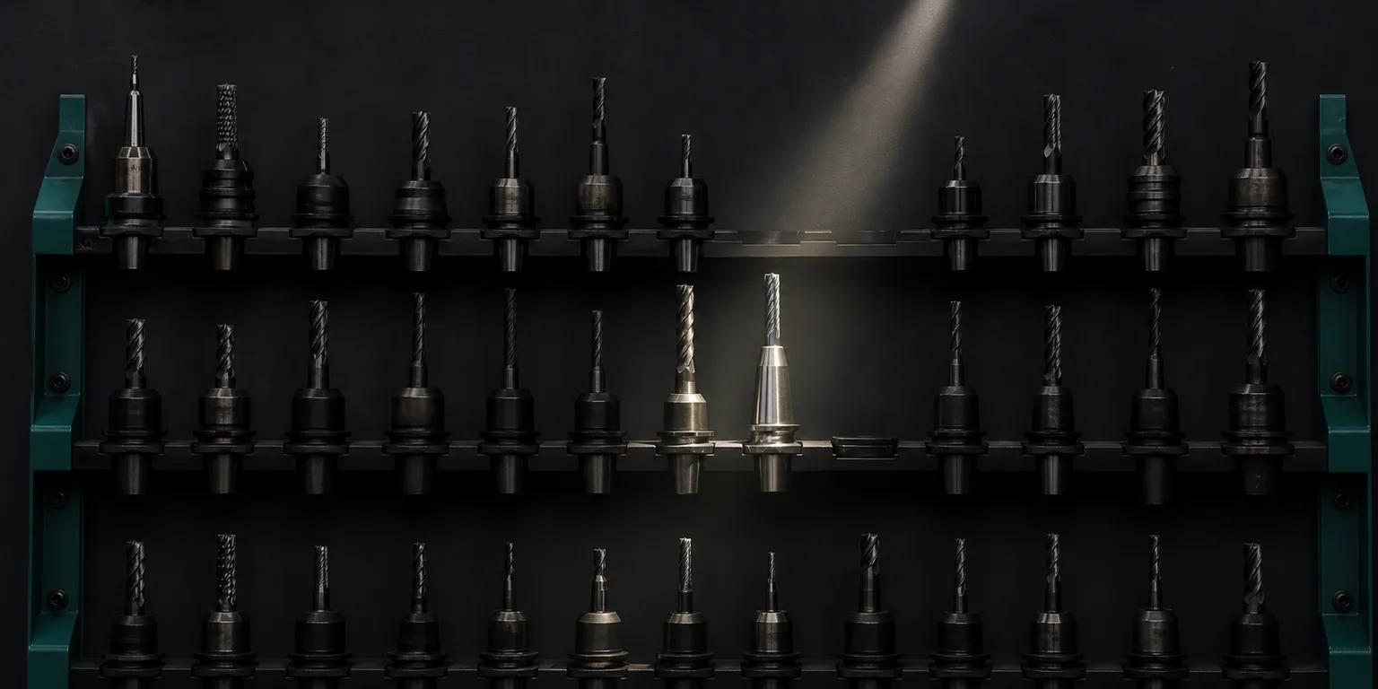
01What is tool management? And what does a tool library record
Tool management means organizing the specification and status of every tool in the shop into searchable, referenceable data, and the full set of operations that keeps it correct; this data list is the tool library. A tool library records not just "which tools we have," but also each tool's code, diameter and flute length, actual tool length after clamping, recommended speeds and feeds, and the corresponding tool-length / radius offset numbers.
Within the framework of manufacturing automation and computer-integrated manufacturing (CIM), tool data is an indispensable part of process planning—deciding which tool to use, which path to take, and how deep to go presupposes that these tool specifications have already been standardized, documented, and made referenceable by the system[1]. In other words, the tool library is the first step in moving "where the tool is, how long it is, how it is used" from the veteran machinist's memory into manageable data, and it is the foundation on which downstream automated programming and simulation can operate.
02Where crashes and quality problems come from when tools aren't on file
In many small and mid-sized CNC shops in Taiwan, tool data is in fact scattered in a machinist's head, on paper cards, or in the controller memory of one particular machine. This may work with one person on one machine, but the moment you need to hand off across machines, shifts, or people, the problems surface:
- Tool-length offsets don't match: when the actual clamped length of a tool differs from what the program assumes, locating the workpiece surface after a tool change goes off, causing anything from out-of-tolerance dimensions to a plunge that crashes into the workpiece or fixture.
- Wrong tool or wrong parameters: if the same hole is machined with a different batch of tools and the speeds and feeds are not adjusted accordingly, it can cause tool marks, edge chipping, or even a broken tool. Metal-cutting-mechanics literature has long noted that feed, speed, and depth of cut must be based on the mechanical and vibration characteristics of the tool-workpiece system, and stepping outside that boundary invites trouble[2].
- Wear and life go untracked: tool wear directly affects dimensional accuracy and surface quality, and without a record of how long a tool has been used and whether it should be changed, you often only discover the tool has gone dull when a part is already scrapped.
The common root cause of all three is that "there is no trustworthy, single source for tool data." What tool management sets out to solve is exactly this: turning tool information from individual experience into shop-wide, auditable data. To understand the cost structure of crashes and simulation protection more fully, see the related article How Much Does One Crash Cost? How Cutting Simulation and AI Verification Stop Accidents Before the Machine.
03Which fields a usable tool library should record
A tool library doesn't need to be big and comprehensive from day one, but a few key fields are non-negotiable. The following are the core fields most often referenced by programming and simulation:
| Field | Content | Why it matters |
|---|---|---|
| Tool code / pocket number | T01, T02… mapped to the magazine pocket | Unique identifier for program tool change (M06) and tool selection in simulation |
| Tool type and geometry | End mill, ball nose, drill, tap; diameter, flute length, flute count, corner radius | Determines which features are machinable and the toolpath calculation |
| Tool length (actual length after clamping) | Length from tool tip to spindle reference | Basis for tool-length offset and plunge / retract heights |
| Tool-length / radius offset number | H, D offset codes | Locates the workpiece surface after a machine tool change |
| Recommended cutting parameters | Speed, feed, depth of cut, feed per tooth | Safe parameter boundaries matched to material and operation |
| Life / wear record | Accumulated cutting time or part count, tool-change date | Tracks tool status and enables preemptive changes to avoid quality drift |
The cutting-parameters field need not be filled in by gut feel—it has a theoretical basis to follow, and the system can suggest starting values by material and tool. For the principles behind this, see How Do You Set Cutting Parameters? The Theory Behind Speed, Feed, and Depth of Cut and How AI Assists. Pinning these parameters to each tool in the library is precisely what lets programming reference them consistently instead of re-guessing every time.
04Tool-length offset and tool life: turning the master's feel into data
Of all the fields, tool length and tool life are the two most easily overlooked yet most often the cause of accidents.
Tool-length offset: a high-risk source of crashes
The tool-length offset tells the machine how long the tool tip is relative to the spindle reference. After a tool change, the machine uses this value to align the coordinate system to the workpiece surface. If the offset value is entered wrong, or the program calls the wrong tool, the actual position of the tip no longer matches what the program expects—during rapid positioning (G00) or plunging, it can crash straight into the workpiece, fixture, or even the machine. Putting tool length into the tool library, so that both the program and the simulation reference the same tool-length data, is the most direct way to reduce this kind of human error.
Tool life and wear: the invisible variable in quality
Tools wear, and wear changes cutting force, dimensions, and surface quality. The CIRP review of machining monitoring notes that tool condition monitoring is an important means of maintaining quality and avoiding unexpected failure in advanced machining, capturing tool wear and breakage status through sensing and data interpretation[3]. For most small and mid-sized shops, you don't have to jump straight to installing online monitoring, but at minimum you should record each tool's accumulated usage and change timing in the tool library, turning "this tool is about due for a change" from the master's feel into data anyone can look up. Only then can quality avoid drifting during handoffs due to an experience gap.
05Why AI programming needs a tool library first
Back to the core question of this article: why is building a tool library so often the first step when adopting AI-assisted programming? The reason lies in the nature of G-code—it only describes the tool's motion path and does not know "which tool is used, how long it is, or what the parameters should be." Without a tool library, AI can only assume tools, and the tool-length offsets, plunge depths, and retract heights it produces may not match the actual tools—everything looks normal in cutting simulation, but it crashes on the machine.
Once the shop's tool library is imported into the AI CAM workflow, things are different. This echoes a basic principle of automation and CIM: the reliability of automated process planning depends on whether tool, machine, and process data have already been standardized and made referenceable by the system[1]. Concretely, after importing the tool library:
- Selecting the correct tools: AI selects tools by drawing features from a tool library of tools that actually exist, rather than assuming an ideal tool that isn't there.
- Planning paths with the correct tool length: plunge, retract, and safe heights are all computed from the real tool length, reducing crash risk from tool-length errors.
- Parameters within safe boundaries: speeds and feeds use the tool library's standard parameters as boundary conditions, rather than letting the model run free.
- Simulation closer to reality: 3D cutting simulation references the same tool data, so the previewed toolpath, interference, and travel checks actually mean something.
In other words, the tool library is the key data foundation that turns the "AI reads the drawing → generates G-code → cutting simulation" workflow from theory into something you can actually run on the machine. The practical order at rollout is simple: first file the codes, tool lengths, and standard parameters of the 30-40 most-used core tools, run the complete workflow on one real plate part, then add the remaining tools and wear records over time. For how the whole machining-preparation workflow connects, see the pillar article The Complete Guide to CNC Auto-Programming: How AI Turns a 2D Drawing into Verifiable G-code.
06FAQ
What is the difference between a tool library and tool management?
A tool library is a data list that records each tool's code, specification, tool length, geometry, and recommended cutting parameters; tool management is the full set of operations built around that list, including creating records, measuring tool length, tracking tool life and wear, and updating data after a tool change. The tool library is the static data foundation; tool management is the process that keeps it continuously correct and referenceable by programming and simulation.
Why must there be a tool library before AI generates G-code?
Because G-code only describes tool motion; it does not know which tool is used or how long the tool is. Without a tool library, AI can only assume tools, and the tool-length offsets and plunge depths it produces may not match the actual tools—it looks fine in simulation but crashes on the machine. Once tool codes, standard lengths, and parameters are imported, AI can select tools that actually exist, plan paths with the correct tool length, and check travel and interference.
Why does a wrong tool-length offset so easily cause a crash?
The tool-length offset tells the machine how long the tool tip is relative to the spindle reference, and it is the basis for locating the workpiece surface after a tool change. If the offset value is entered wrong or the wrong tool is used, the actual tip position no longer matches what the program expects, and during rapid positioning or plunging it can crash straight into the workpiece, fixture, or machine. Putting tool length into the tool library and passing simulation and human review before running is how you stop this kind of error before the machine.
A small shop has many tools and changes them often—can a tool library really be maintained?
We recommend building the commonly used core tools first, without registering the entire inventory at once. Filing the codes, tool lengths, and standard parameters of the 30-40 most-used tools already covers most jobs; after that, add more each time you change or purchase tools, and refine over time with life and wear records. The key is making the tool library the single data source that programming and simulation reference, rather than something scattered in people's heads or on paper.
Get notified when new articles and video guides go live—no inbox flooding, unsubscribe in one click.
READY FOR A CONTROLLED PILOT?
Hand your tool library to AI, and give tool selection and crash prevention a basis to work from
From tool codes and tool lengths to cutting parameters, we help turn your shop's tool data into a data foundation that AI can reference for tool selection, code generation, and simulation.
Contact a deployment consultant Training courses07References
- Groover, M. P. (2019). Automation, Production Systems, and Computer-Integrated Manufacturing (5th ed.). Pearson.
- Altintas, Y. (2012). Manufacturing Automation: Metal Cutting Mechanics, Machine Tool Vibrations, and CNC Design (2nd ed.). Cambridge University Press.
- Teti, R., Jemielniak, K., O'Donnell, G., & Dornfeld, D. (2010). Advanced monitoring of machining operations. CIRP Annals, 59(2), 717–739.