INSPECTION & QUALITY CLOSED-LOOP
Done Machining, So You're Done? Dimensional Measurement, As-Measured Comparison, and the Quality Closed Loop
01What are CNC inspection and the quality closed loop?
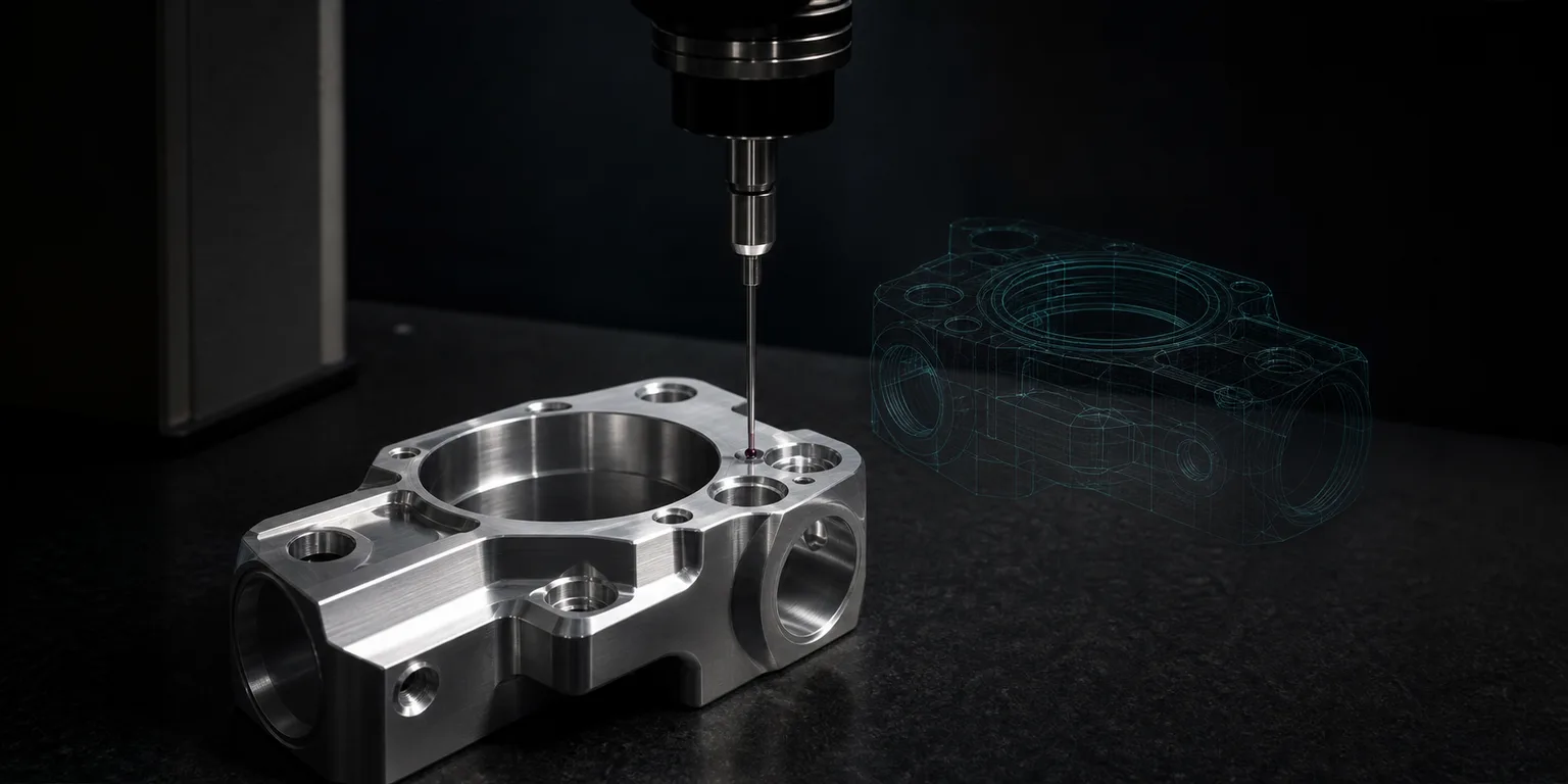
CNC inspection is the process of confirming, after a workpiece is machined, whether its actual dimensions and geometric features meet the drawing requirements using gauges or measuring equipment. Within it, dimensional measurement and as-measured comparison are the two most central actions—the former obtains the actual values, the latter checks those values back against the tolerance bands of the drawing callouts to make a pass/fail decision. The "quality closed loop (closed-loop quality)" goes a step further: it feeds the deviation information obtained from measurement back into machining prep and process parameters, so the next batch of parts is more stable, rather than just being filed away once measured.
Classic manufacturing-engineering texts treat measurement and inspection as an inseparable part of the manufacturing system: achieving dimensional accuracy and surface integrity depends on the collaboration of machining, measurement and quality control, not just on how precisely the machine cuts[1]. In other words, measurement isn't an accessory step to machining—it's the only objective basis for judging "whether what you made is actually right."
02Why "done machining, so you're done" is dangerous
Many shops compress measurement into "sample a few key dimensions and check with calipers." This may still pass on simple parts, but the moment you hit an order with tight tolerances, high geometric requirements or strict customer-side audits, it exposes three blind spots:
- Measuring only what's easy, not what matters: calipers can measure length, width and bore diameter, but can't assess geometric tolerances like flatness, perpendicularity or position; miss these, and a part whose dimensions all "pass" may still fail to assemble.
- Ignoring measurement uncertainty: measurement itself has error. When a measured value is close to the tolerance boundary, judging it a pass without accounting for the gauge's uncertainty is equivalent to shifting the risk onto the customer.
- Filed away once measured, with no feedback: even if every part is measured, if the data doesn't connect back to machining, systematic deviations (tool wear, thermal deformation) recur batch after batch, and quality is forever propped up by after-the-fact screening.
The first two are measurement-method problems; the third is the fundamental one—it determines whether a shop stays at "detecting defects" or moves toward "preventing defects." This is exactly the core the quality closed loop is meant to solve.
03The fundamentals of dimensional measurement: gauges, CMM and measurement uncertainty
Choosing the right measurement method is the precondition for as-measured comparison to mean anything. The common measurement levels are roughly as follows:
| Measurement method | Suited features | Limits and cautions |
|---|---|---|
| Caliper / micrometer | General linear dimensions, outside diameter, hole depth | Fast but affected by feel; not suited to tight tolerances or geometric measurement |
| Plug/pin gauges, thread gauges | Bore diameter, go/no-go decision for threaded holes | A functional go/no-go check; does not give an actual value |
| Coordinate measuring machine (CMM) | Position, form and orientation tolerances, complex surfaces | High accuracy, but needs a program and fixture; measurement and environmental conditions must be controlled |
| Optical/projection measurement | Thin-part profiles, small features | Non-contact, suited to easily-deformed parts |
Whichever you use, you must confront measurement uncertainty: any measured value is "the true value plus a band of uncertainty." When the workpiece's tolerance band is very narrow and the measured value sits close to the upper or lower limit, the gauge's own uncertainty may eat up much of the tolerance, and then "just barely passing" is actually unreliable. Manufacturing-engineering texts therefore stress that a measurement system's capability must be commensurate with the tolerance of the feature being measured—the choice of measurement method is itself part of the quality decision[1]. High-precision or geometrically demanding dimensions usually need a CMM or dedicated gauges, measured under controlled conditions.
04The per-callout as-measured comparison table: a shared language for drawing and part
Once you have the measured values, the next step is to make them something the customer "understands and trusts." The key tool here is the per-callout as-measured comparison table: it maps every dimensioned callout on the drawing and its tolerance, item by item, to the actual measured value and a pass/fail decision, making it obvious at a glance where each dimension sits within its tolerance band. Compared with a simple report that just lists a few numbers, the per-callout comparison table aligns the "drawing language" with the "part data," making it the clearest communication language between drawing and part.
In this product's machining package, this per-callout as-measured comparison table is delivered together with the verification report as the formal document for cross-referencing drawing and part. What must be specifically bounded is this: the measurement itself is carried out by shop-floor personnel following standard procedures—the system does not automatically connect to or operate a coordinate measuring machine. In other words, AI and the package are responsible for structuring "which dimensions to measure, how to cross-reference, and how to present," while the actual physical measurement and final pass/fail decision remain in the hands of QA personnel.
A usable per-callout comparison table usually contains: callout number and location, nominal dimension, upper and lower tolerance, measured value, deviation, pass/fail, and the gauge used. The numbers correspond one-to-one with the drawing, so during a customer audit each point can be traced back item by item, instead of facing a heap of isolated numbers.
05From measurement to the quality closed loop: model-to-part feedback
The real value of measurement data lies in connecting it back to machining prep. When a batch of parts' measured values systematically skew toward the same side of the tolerance band, it's usually not chance but a traceable cause—tool wear, thermal deformation or tool-length-offset settings. Feed those deviations back into the next round of tool offsets, cutting parameters and program, and subsequent batches become more stable—this is the quality closed loop: measurement is no longer the endpoint, but the input for the process to self-correct.
This loop of "physical-world measurement → feedback to the virtual model and decisions" is precisely the core of the digital twin. Digital-twin-driven manufacturing emphasizes continuous comparison of model and part, feeding physical-side measurement and operational data back into the virtual model to optimize design and manufacturing decisions[2]. From the machining-prep angle, the per-callout comparison table is the most structured piece of "part-side" data in this loop: it makes the difference between model expectation and actual result quantifiable and feedable.
Seen from the larger manufacturing system, this architecture that tightly couples sensing/measurement information with computational decisions is precisely what the smart-manufacturing literature describes as cyber-physical systems—through the two-way linkage of physical processes and computational models, the manufacturing system gains the ability to self-sense and adapt[3]. The quality closed loop can be seen as this larger architecture's concrete landing in the "machining–measurement" segment: first make measurement data structured and feedable, and only then is there a chance to extend toward more automated adaptation.
06What AI can help with, and what it can't replace
Once the quality closed loop is clear, AI's reasonable role is obvious: what it accelerates is the "machining-prep side" and the "data-collation side," not replacing physical measurement.
- What it can help with: structuring the drawing callouts and automatically generating the framework of the per-callout comparison table; at the modeling stage, having an independent AI cross-check the 3D model dimensions against the 2D drawing callouts one by one and proactively flag anomalies, reducing manual collation and missed checks; and aggregating past deviations into feedable trends for the machinist to reference when adjusting tool offsets and parameters.
- What it can't replace: the actual physical measurement, gauge selection and measurement-uncertainty assessment; the final interpretation of geometric tolerances and datums; and the sign-off on pass/fail. To emphasize—the system does not automatically connect to or operate a coordinate measuring machine; the measurement action and decision remain shop-floor QA expertise.
In other words, AI makes "what to measure, how to cross-reference, and which way the deviation trends" clear and traceable, while the shop-floor expert retains final responsibility for measurement and decision. When the two divide the labor properly, the quality closed loop can be both efficient and audit-proof.
07FAQ
For CNC inspection, is it enough to just measure a few key dimensions with calipers?
Sample-checking key dimensions is the minimum bar, but it isn't enough to constitute quality assurance. Complete inspection should cover all toleranced callouts, geometric tolerances and datum relationships, and record the gauges and measurement conditions. Calipers can't assess form and position tolerances; features with high precision or geometric requirements usually need a CMM or dedicated gauges, and pass/fail can only be judged after accounting for measurement uncertainty.
What is a per-callout as-measured comparison table, and how does it differ from an ordinary inspection report?
A per-callout as-measured comparison table maps every dimensioned callout and tolerance on the drawing, item by item, to the measured value and a pass/fail decision, making it obvious where each dimension sits within its tolerance band. In this product's machining package, it is delivered together with the verification report as the language for drawing-vs-part communication; but the measurement is carried out by shop-floor personnel following standard procedures—the system does not automatically connect to or operate a coordinate measuring machine.
How do measurement data become a basis for improving machining, rather than being filed away once measured?
The key is to connect measurement results back to machining prep, forming a quality closed loop. When measured values systematically skew toward one side of the tolerance band, this usually reflects traceable causes such as tool wear, thermal deformation or offset settings; feeding deviations back into the next round of tool offsets, parameters and program makes subsequent batches more stable. The digital twin is precisely about using continuous model-to-part comparison to feed physical measurements back into the virtual model and process decisions.
What role does AI play in dimensional measurement and as-measured comparison, and where is the line?
AI's reasonable role is on the machining-prep side—structuring the drawing callouts, generating the per-callout comparison-table framework, and at the modeling stage cross-checking the 3D model dimensions against the drawing callouts and flagging anomalies, reducing manual collation and missed checks. Actual physical measurement, gauge selection and uncertainty assessment remain shop-floor expertise; the system does not automatically connect to or operate a coordinate measuring machine, and the final pass/fail decision is the responsibility of QA personnel.
Get notified when new articles and video reviews go live—no inbox flooding, one-click unsubscribe.
CLOSE THE LOOP ON YOUR DRAWINGS
Connect measurement data back to machining prep—no more filing it away once measured
From structuring drawing callouts and the per-callout comparison table to model-to-part cross-verification, we help define the starting point of a quality closed loop that fits your shop.
Contact an onboarding advisor Training courses08References
- Kalpakjian, S., & Schmid, S. R. (2020). Manufacturing Engineering and Technology (8th ed.). Pearson.
- Tao, F., Cheng, J., Qi, Q., Zhang, M., Zhang, H., & Sui, F. (2018). Digital twin-driven product design, manufacturing and service with big data. The International Journal of Advanced Manufacturing Technology, 94, 3563–3576.
- Monostori, L., Kádár, B., Bauernhansl, T., Kondoh, S., Kumara, S., Reinhart, G., Sauer, O., Schuh, G., Sihn, W., & Ueda, K. (2016). Cyber-physical systems in manufacturing. CIRP Annals, 65(2), 621–641.