TOLERANCE & GD&T READING
Tolerances and GD&T Reading: Can AI Understand Geometric Tolerances?
01What are tolerances and GD&T? Why they decide whether a part assembles
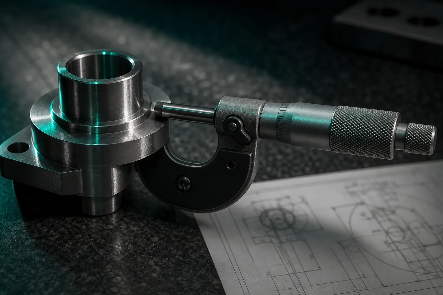
A tolerance is the allowable range of variation for a dimension, while GD&T (Geometric Dimensioning and Tolerancing) goes a step further to control form, orientation, location, and runout—for example flatness, straightness, position, perpendicularity, and concentricity. When a customer asks "can AI read CNC tolerances and GD&T," what they really care about is this: the parts we ship will assemble, will pass inspection, and won't scrap an entire batch because one position tolerance is out.
Classic manufacturing-engineering textbooks note that tolerances are the bridge between design function and manufacturing cost: the tighter the tolerance, the higher the machining, measurement, and inspection cost, so a tolerance has never been just "a number drawn on the print"—it carries an engineering decision about assembly and function (Kalpakjian & Schmid, 2020)[1]. That is exactly why tolerance reading cannot be treated as OCR that reads out numbers—it requires understanding design intent.
02The division of labor between general and geometric tolerances: ISO 2768 and GD&T
Tolerances on an engineering drawing usually fall into two layers. The first layer is general tolerances: the linear and angular dimensions that are not individually toleranced, governed by ISO 2768 general tolerances and applying the corresponding class range based on the tolerance grade specified in the title block (such as f for fine, m for medium, c for coarse)[2]. The second layer is individually marked tolerances and geometric tolerances: critical mating surfaces carry upper and lower deviations, or specify form-and-position requirements with a GD&T frame.
| Tolerance type | Typical source | Reading difficulty |
|---|---|---|
| General tolerance (unmarked dimensions) | ISO 2768 + title-block grade | Low: clear rules, look up and apply |
| Individual linear tolerance (± value) | Marked directly beside the dimension | Medium: must be matched to the right dimension |
| Geometric tolerance GD&T (form/position frame) | Feature control frame + datum | High: involves the datum system and assembly intent |
This layering matters because it decides where AI should reasonably apply effort: the layer with clear, look-up rules is best handed to automation; the layer that involves engineering judgment should be left to people.
03What AI can read: standard features and general tolerances
The good news is that AI is already quite reliable on the "regularized" parts of a drawing. Machining feature recognition has been a topic in CAD/CAM integration research for over thirty years, and deep learning has recently made breakthroughs—the FeatureNet proposed by Zhang et al. uses a 3D convolutional neural network to recognize milling features (holes, slots, islands, pockets, and so on) and reaches about 96.7% recognition accuracy on a benchmark dataset (Zhang, Jaiswal & Rai, 2018)[3]. This means that "letting AI understand which standard machining features appear on a drawing" has a feasible foundation, both academically and in engineering practice.
Mapped to tolerance reading, what AI can currently handle reliably includes:
- Recognizing standard machining features: holes, tapped holes, counterbores, slots, pockets, and so on, and obtaining their nominal dimensions.
- Applying general tolerances: for dimensions with no marked tolerance, automatically bringing in the corresponding class range by ISO 2768 grade[2], as the default for 3D modeling and machining preparation.
- Extracting individually marked ± tolerances: matching the upper and lower deviations beside a dimension to the correct feature.
- Extracting the symbols and values inside a GD&T frame: reading out the fact that "there is a position tolerance of 0.05 here, datums A-B."
For how far AI drawing reading can go and how it differs across drawing quality, see the related article Can a Phone Photo Build a 3D Model? What AI Drawing Recognition Can and Can't Do.
04What AI can't read: GD&T, datums, and assembly intent
The line is also clear: reading out a GD&T symbol is not the same as understanding GD&T. The core of geometric tolerancing is the datum reference frame—the same position tolerance of 0.05 measured from datum A versus from a B-C combination can produce completely different results and completely different assembly behavior. How the datum is chosen, and which mating relationship it corresponds to, is decided by the designer based on functional intent, and it may not be fully written on the drawing.
A tolerance is essentially a trade-off between function and cost, and reading it requires understanding how the part assembles, how it is loaded, and which surface is the critical mating surface (Kalpakjian & Schmid, 2020)[1]. For this reason, the following items should still be confirmed by an engineer rather than finalized automatically by AI:
- Special tolerances and critical mating dimensions: press fits, slip fits, sealing faces, and so on, which involve the actual behavior after assembly.
- Datum setup for geometric tolerances: the choice of datum plane / datum axis and the measurement method.
- Tolerance stack-up and functional judgment: whether the assembly requirement is still met after multiple tolerances accumulate.
To be honest, this is exactly why separating "the regularized recognition AI is good at" from "the intent judgment engineers are good at" makes the overall workflow more reliable than either all-manual or all-automated.
05Making AI read more accurately: agreed-color flagging and drawing conventions
Once the line is clear, the next question is: how do we push the part AI reads accurately to its maximum within that line? Two practices are especially effective.
First, provide native electronic drawing files such as DWG. In native files, dimension callouts, tolerances, and GD&T frames are all structured data, giving the highest recognition reliability; PDFs and photos increase the risk of misreads due to vectorization, OCR, and perspective distortion, so tolerance frames need focused review.
Second, use agreed-color flagging for high-precision holes and critical mating dimensions. Marking key features on the drawing with a pre-agreed color (for example, giving all the tightest-tolerance holes the same color) lets the recognition workflow flag them first and avoid treating them as ordinary holes, noticeably improving the recognition reliability of high-precision dimensions. This practice makes "which dimensions can least afford an error" explicit in a way machines can easily distinguish—effectively establishing a clear handoff mark between AI and the engineer.
06Human-in-the-loop: the final gate for tolerance reading
Turning the line above into a workflow is human-in-the-loop: AI is responsible for reading the drawing, recognizing standard features, bringing in general tolerances, extracting individual tolerances and GD&T frames, and proactively flagging items that are uncertain or need human confirmation; the engineer is responsible for the final reading and sign-off of special tolerances, datum setup, and assembly intent. Critical mating dimensions and GD&T must be built into a human review checkpoint so that responsibility is clear.
Downstream of tolerances comes measurement and the quality closed loop—the tolerances AI brings in must ultimately be verified against actual measurements to confirm they are met; for that, see the related article Done Machining Means Done? Dimensional Measurement, Actual-Value Comparison, and the Quality Closed Loop. And tolerance reading is only one link in AI machining preparation; the complete "2D drawing → 3D model → G-code → simulation → verification" workflow is laid out in the pillar article The Complete Guide to CNC Auto-Programming. To see AI's place across the whole machining-preparation chain more fully, you can also go back to the product home page or browse the blog index.
07FAQ
Can AI automatically read GD&T (geometric tolerances)?
AI can recognize that a geometric tolerance frame appears on the drawing (such as flatness, position, or perpendicularity) and extract its value, but "which datum this position tolerance should be measured from and what assembly intent it corresponds to" involves design purpose and should still be confirmed by an engineer for now. Reading GD&T is not just reading out symbols; it means understanding the datum system and functional requirements, and that layer remains human expertise.
For dimensions with no tolerance marked on the drawing, what tolerance does AI apply?
Linear and angular dimensions that are not individually toleranced are usually handled under ISO 2768 general tolerances, applying the corresponding class range based on the tolerance grade specified in the drawing title block (such as f, m, or c). AI can bring in general tolerances by default on this basis, but if such a dimension is actually a critical mating surface, an engineer should still mark it explicitly with an individual tolerance or a geometric tolerance.
How can I make AI recognize the tolerances of high-precision holes more accurately?
We recommend flagging high-precision holes or critical mating dimensions on the drawing with a pre-agreed color, so the recognition workflow prioritizes them and avoids treating them as ordinary holes; at the same time, provide native electronic drawing files such as DWG first, so dimensions and tolerances enter the system as structured data. Both practices improve recognition reliability and shorten manual review time.
When a tolerance is misread, is it the AI's fault or the engineer's?
In the correct deployment model, AI only reads the drawing, extracts dimensions, and brings in general tolerances, and it proactively flags uncertain items; the final reading of tolerances, datums, and special processes is signed off by an engineer. That is why critical mating dimensions and GD&T must be built into a human review checkpoint—let AI speed up preparation while professionals retain the final judgment and responsibility.
Get notified when new articles and video guides go live—no inbox flooding, unsubscribe in one click.
READY FOR A CONTROLLED PILOT?
Take one real drawing and see how far AI can go reading tolerances
From general tolerances and critical mating dimensions to GD&T markings, we help define what to hand to AI for acceleration and what to reserve for engineer sign-off, designing a review workflow that fits your shop.
Contact a deployment consultant Training courses08References
- Kalpakjian, S., & Schmid, S. R. (2020). Manufacturing Engineering and Technology (8th ed.). Pearson.
- ISO 2768-1:1989. General tolerances — Tolerances for linear and angular dimensions without individual tolerance indications. International Organization for Standardization.
- Zhang, Z., Jaiswal, P., & Rai, R. (2018). FeatureNet: Machining feature recognition based on 3D Convolutional Neural Network. Computer-Aided Design, 101, 12–22.