CNC MACHINING FUNDAMENTALS
Touch-Off and Work Coordinate Systems: G54 to Tool-Length Offset, Explained
01What is touch-off? And what are work coordinates?
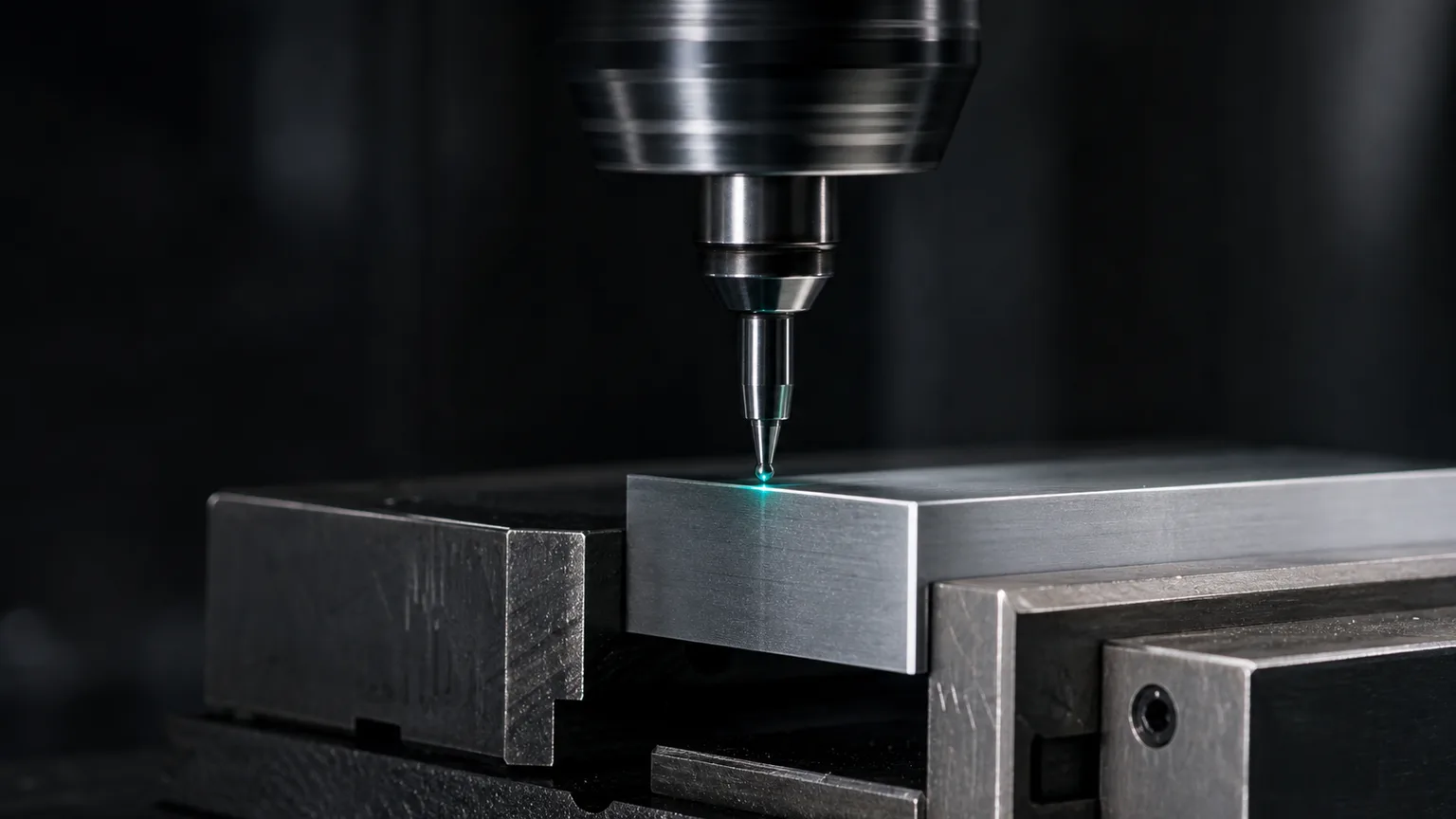
Touch-off (work offset setting) is one of the most critical preparation steps before a CNC job runs: measuring "the workpiece's actual position on the machine" and "the length of each tool," and writing them into the controller so that the coordinates in the program map to the correct positions in the real world. Every X/Y/Z value in a machining program is laid out with a zero at some agreed datum point on the workpiece — the work origin[3]; this coordinate set, referenced to the work origin, is what we call work coordinates.
The problem is that after the machine powers up and homes, the controller only has one set of "machine coordinates" in mind and has no idea where on the vise you clamped the workpiece today. What touch-off does is connect these two things for the controller: first measure the work origin's coordinate value in the machine coordinate system and write it into G54, then measure each tool's tool-length offset one by one. Without correct touch-off, no matter how precise the program is, it just sends the tool to the wrong place.
02Machine vs work coordinates: the roles of the two systems
To understand touch-off, you first have to distinguish the roles of the two coordinate systems:
| Coordinate system | Where the zero is | Who decides it | Purpose |
|---|---|---|---|
| Machine coordinate system | Machine origin (the home position) | Fixed when the machine is built | Lets the controller describe the actual slide position, tool-change point and travel limits |
| Work coordinate system | Work origin (set by the operator) | Decided during touch-off | The datum for programming and machining dimensions |
Manufacturing engineering textbooks are clear on numerical control: an NC program must be built on a well-defined coordinate datum, and it is the operator's responsibility to define the relationship between the workpiece datum and the machine coordinates so that the tool motion described by the program means something (Kalpakjian & Schmid, 2020)[1]. In other words, machine coordinates are the machine's "absolute address," work coordinates are the machining "relative address," and touch-off is what draws an equals sign between them. When an engineer writes a program, they only need to focus on work coordinates and not worry about which corner of the machine the workpiece sits in today — that is exactly why work coordinate systems exist.
03What are the G54–G59 work coordinate systems?
In the G-code program format defined by ISO 6983, work coordinate systems are called up by a set of preparatory function codes (G codes); G54 to G59 are the six standard-defined storable work coordinate systems[3]. Their content is identical; they differ only in that each can remember one independent work origin:
- A single workpiece: G54 alone is enough. During touch-off, write the work origin into G54, call G54 at the start of the program, and all subsequent coordinates reference it.
- Multiple workpieces in one setup: When four parts are lined up on the vise, or there are several stations on a fixture, you can store each work origin separately in G54, G55, G56… and switch stations with G54–G59 in the same program, without recalculating coordinates for each part.
- Extended work coordinate systems (G54.1 P__): When six are not enough, some controllers provide extended coordinate systems for high-volume batch machining with many parts lined up.
Clearing up a concept: G92 can also set work coordinates, but it "declares" the current tool position as a certain coordinate value — a temporary setting that easily drifts after a restart or a misoperation. Modern machining generally relies on work coordinate systems like G54–G59 that are "registered in memory," which are more stable and easier to manage. To understand the G-code command family and ISO 6983 more fully, read on with our complete G-code primer.
04Common methods for centering, edge-finding and Z-axis touch-off
In practice, touch-off splits into two things: finding the work origin in the XY plane (centering/edge-finding), and setting the Z-axis zero (the height at which the tool tip touches the top surface of the workpiece). Here are the conceptual methods common on the shop floor:
The XY plane: edge-finding and centering
- Edge finder: Mechanical or electronic. The mechanical type judges the boundary by the moment a spinning needle deflects and then suddenly snaps into alignment as it just contacts the workpiece edge; the electronic type emits a signal at contact conduction. Once you catch two opposite edges, you can compute the boundary coordinate.
- Wiggler / centering: To find the center of a symmetric workpiece or round hole, touch the two opposite edges separately and take the midpoint as the X or Y origin; this "take the midpoint" act is centering. Many controllers have a built-in centering-measurement cycle that automatically computes the center after touching two edges and writes it into G54.
- Touch probe: The most automated. The machine touches multiple points with the probe following a cycle, directly back-calculates the origin and writes it into the work coordinates, minimizing human feel errors.
The Z axis: touching off the top surface
- Paper method: Slip a thin sheet of paper between the tool tip and the workpiece top surface, lower the tool slowly until the paper is just pinched and there is resistance when you tug it, and estimate that as the contact point. Simple but affected by feel and paper thickness, so its precision is low.
- Tool setter / Z-axis setter: A fixed-height gauge or electronic tool setter placed on the workpiece top surface reads a value when the tool tip presses to a specified travel; subtracting the instrument height gives the Z zero, with clearly better repeatability than the paper method.
The authoritative text on cutting mechanics and CNC design reminds us that one source of machining precision is the correct establishment of the relative position between the tool and the workpiece; touch-off error adds directly onto the finished dimensions and becomes a systematic deviation (Altintas, 2012)[2]. So the choice of touch-off method is essentially a trade-off between "speed" and "repeatability" — the paper method is enough for low-tolerance parts, while tight tolerances are worth investing in a tool setter or probe.
05How G43 tool-length compensation and the H value work
A machining center easily holds a dozen or twenty tools, each protruding from the spindle by a different length. Re-touching the Z zero every time you change a tool is both slow and error-prone. Tool-length compensation exists to solve this: store each tool's length difference in its own compensation register, and the program calls the corresponding compensation amount with G43 plus an H value, so the controller automatically adjusts the Z-axis position to the correct height.
- G43: Enables positive tool-length compensation, usually written as
G43 H01 Z___, meaning it applies the tool length in compensation register 01. - H value: Corresponds to the column number of the offset table, generally kept consistent with the tool number (T01 uses H01) to avoid confusion. The controller adds the tool length registered in that column into the Z-axis calculation.
- G49: Cancels tool-length compensation, commonly used before a tool change or at the end of the program.
ISO 6983 clearly defines the format of such preparatory functions and address words; G43/G49 and their H address are precisely part of the standard program format[3]. In practice there are two record-keeping approaches: one is to measure each tool's length independently and set the Z work zero uniformly with G54; the other is to zero on a reference tool and store relative differences for the rest. Either way, the H value must strictly correspond to the actual tool — the core key when we discuss crashes next.
06Common touch-off errors and their link to crashes
Touch-off is one of the most concentrated sources of crash incidents, because its errors often only reveal themselves at the moment the tool has already plunged and contacted the workpiece. Common errors include:
- Wrong H value called or recorded: The program calls H05 but it corresponds to another tool's length, so the actual Z-axis height deviates from expectation — too high leads to air cutting or undersize, too low can drive straight into the workpiece or fixture.
- Wrong work coordinate system selected: A station that should use G55 keeps using G54, and the entire machining position shifts to the wrong region, possibly hitting the fixture or running off the workpiece.
- Z zero set on the wrong face: Taking the raw stock top as an already-machined datum face, or forgetting to subtract the tool-setter height, causes an overall Z shift.
- Forgetting to cancel or enable compensation (missing G43/G49): A leftover compensation state carries over to the next tool, throwing the Z height completely off.
The common thread of these errors is "the number is wrong, but the machine executes it faithfully." Pre-machining cutting simulation can intercept most such geometric errors before the machine runs — for the actual cost of a crash and how simulation stops incidents before the machine runs, read on with how much does one crash cost? How cutting simulation and AI verification stop incidents before the machine runs. The core principle stays the same: once a touch-off value is written wrong, the controller will not judge whether it is reasonable for you; only simulation and manual review form a second line of defense.
07How a tool library with recorded lengths reduces compensation errors
Since most touch-off crashes stem from "the H value not matching the actual tool," the most effective prevention is to make the correspondence between tool length and compensation number standardized, queryable and checkable, rather than relying on the operator's on-the-spot memory. This is exactly the value of building a shop tool library.
When this product generates G-code, it builds on a shop-specific tool library: each tool's code, standard length, compensation number and cutting parameters are recorded in advance, so when the AI generates the program and simulates it, it selects tools that actually exist and the correct H correspondence — making "the tool the program calls" and "the tool in the offset table" consistent from the source and sharply reducing the chance of calling the wrong H value. The complete practice of recording tool lengths — code rules, standard-length management and how to align with the controller's offset table — is organized in tool library management.
An honest boundary: Touch-off itself is still a manual or probe action on the machine; this product will not press the touch-off button on the machine for you. What it does is "machining preparation" — fixing and verifying the correspondence between tool length, compensation number and work coordinates in the program and simulation ahead of time, so that touch-off on the machine has a correct, checkable reference and less room for human recording errors. Tolerances, datums and final on-machine confirmation are still gatekept by on-site professionals.
08FAQ
What is touch-off, and why is it always necessary?
Touch-off is the act of telling the controller the workpiece's actual position and the tool lengths. Program coordinates reference the work origin, but at power-up the machine only knows machine coordinates; touch-off means measuring where the work origin falls in machine coordinates, writing it into G54, and registering each tool's tool-length offset. Without correct touch-off, no matter how perfect the program, the tool will machine in the wrong place.
What is the difference between G54 and G59? Can I use only G54?
G54–G59 are six work coordinate systems that are identical in content but can each store one work origin. For a single workpiece, using only G54 is perfectly fine; only when clamping multiple parts in one setup or running several stations do you use G55, G56… to record different origins, switching between G54–G59 in the program to skip recalculating coordinates.
What happens if the H value for G43 tool-length compensation is set wrong?
The H value corresponds to a tool-length compensation register. Calling the wrong H number, or a tool length in the offset table that does not match the actual tool, makes the actual Z-axis height deviate from what the program expects: too high leads to air cutting or undersize, too low can drive straight into the workpiece or fixture. This is one of the most common causes of crashes on the shop floor, making pre-machining simulation and tool-length record checks especially critical.
What is the difference between a wiggler, an edge finder and the paper method?
All three are ways to find a datum or center. An edge finder (mechanical/electronic) judges the moment of contact with the workpiece edge by needle deflection or a signal; centering combined with edge-finding locates the center of a symmetric workpiece; the paper method estimates the Z zero by the feel of a thin sheet being pinched at light contact — simple but low in precision. High-precision needs switch to a tool setter or measuring probe to reduce feel errors.
Get notified when new articles and video guides go live — no inbox flooding, one-click unsubscribe. (newsletter in Chinese)
READY FOR A CONTROLLED PILOT?
Get tool lengths and work coordinates right before the machine runs
From building the tool library and mapping compensation numbers to planning work coordinates, we help make the touch-off reference standardized and checkable, reducing human recording errors and crash risk.
Contact an onboarding advisor Training courses09References
- Kalpakjian, S., & Schmid, S. R. (2020). Manufacturing Engineering and Technology (8th ed.). Pearson.
- Altintas, Y. (2012). Manufacturing Automation: Metal Cutting Mechanics, Machine Tool Vibrations, and CNC Design (2nd ed.). Cambridge University Press.
- ISO 6983-1:2009. Automation systems and integration — Numerical control of machines — Program format and definitions of address words. International Organization for Standardization.