THIN-WALL MACHINING
Thin-Wall Machining: The Causes of Distortion and Chatter, and How to Counter Them
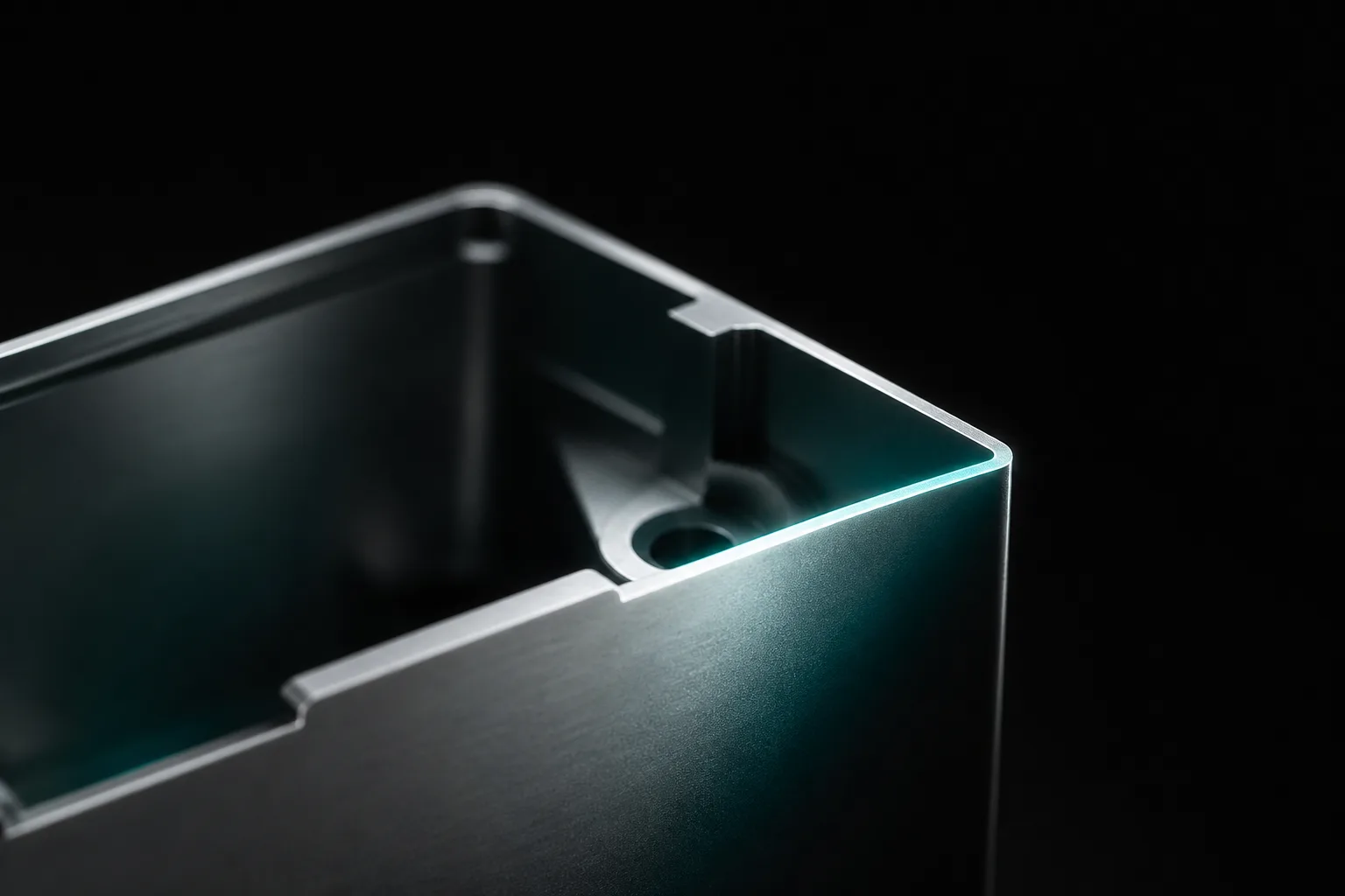
01Why are thin walls hard to machine? Rigidity, cutting force, and chatter
The difficulty of thin-wall machining can be summed up in one sentence: the thinner the wall, the lower the rigidity. The second moment of area drops with the cube of wall thickness, so a wall just a few millimeters thick resists bending far less than intuition suggests—when the tool applies cutting force, the workpiece is pushed away like a spring, and when the force is removed at measurement it springs back, so a gap opens up between "the path the program runs" and "where the workpiece is actually cut," and dimensions drift.
More troublesome is vibration. The authoritative texts on cutting mechanics and machine-tool vibration point out that the stability of a machining system depends on the rigidity and dynamic characteristics of the tool-workpiece system; when structural rigidity is insufficient, the system easily enters regenerative chatter—the waviness left by the previous revolution makes the next revolution's chip thickness vary periodically, and the vibration amplifies itself, commonly called "chatter" (Altintas, 2012)[1]. A thin wall is precisely the weakest link in rigidity, so the same tool and the same parameters that are stable on solid stock can start to squeal on a thin wall. Understanding this makes it clear why thin-wall countermeasures almost all revolve around two main lines: "lowering cutting force" and "raising effective rigidity."
02The three sources of thin-wall distortion
Breaking thin-wall distortion apart, it actually comes from three different forces, each handled differently:
- Cutting-force distortion: the radial component of the cutting force pushes the thin wall outward (or inward) as the tool cuts. This is elastic deformation in the moment of machining; the greater the depth of cut, the duller the tool, and the more aggressive the feed, the more it's pushed away. Manufacturing-engineering textbooks remind us that cutting force rises with feed and depth of cut, and that the rigidity of the workpiece and fixtures must be factored in when choosing machining conditions (Kalpakjian & Schmid, 2020)[2].
- Clamping-force distortion: clamping too tightly to hold a thin wall in place is like bending the workpiece into a curve before machining even begins; once machining is done and the fixture is released, the part springs back, so what was "flat during machining" becomes "curved after release." The location of the clamping points and the pressure distribution are often more critical than how tightly you clamp.
- Residual-stress distortion: metal stock (especially rolled or forged parts) already contains residual stress internally. When roughing removes a lot of stock, the existing stress balance is broken and redistributes, and the workpiece warps once the fixture is released—this distortion isn't visible during machining and only emerges after unloading, which is what makes it most catch you off guard (Kalpakjian & Schmid, 2020)[2].
These three often act at once and are coupled to each other: large cutting force calls for tighter clamping, which worsens clamping distortion; the more stock removed, the more pronounced the residual-stress release. So thin-wall countermeasures are rarely a single move, but a set of mutually coordinated process arrangements.
03Countermeasure logic: symmetry, light cuts, allowance, even clamping
The following are general-rule approaches, not a specific parameter table—actual depth of cut, number of passes, and clamping method still depend on the material, wall thickness, and machine condition:
Symmetric stock removal to balance stress release
As much as possible, remove material from both sides of the workpiece symmetrically and alternately, rather than cutting one side all the way and then the other. Symmetric stock removal lets the release of residual stress balance out and reduces one-directional warping; a common approach is to leave a little allowance on each side and alternate passes, keeping the part in a more balanced state throughout.
Light layered cuts to keep the force per cut low
Rather than taking one very deep cut, take multiple passes with smaller radial and axial depths of cut. As the force per cut drops, so do both the amount the thin wall is pushed away and the risk of entering chatter. This also echoes the intuition of stability theory: lowering chip thickness shrinks the excitation energy and makes it easier for the system to stay in the stable zone (Altintas, 2012)[1].
Rough first, finish later, and leave a finishing allowance
Separate roughing from finishing, and deliberately leave a finishing allowance before the finishing pass. The intent: roughing inevitably causes distortion and stress release, so let that happen first; once the part has "settled," use a light finishing cut to bring out the final dimensions and correct the previously accumulated distortion in the last cut. When necessary, you can arrange to release and then lightly re-clamp between roughing and finishing to let the stress fully release.
Even clamping: soft jaws, vacuum, and low-stress fixturing
A thin wall dreads localized force. Wrapping it with soft jaws over a larger contact area, using a vacuum chuck to hold the workpiece against a flat surface, or providing full-face support with low-melting-point alloy or wax all distribute the clamping force more evenly and avoid bending the workpiece into a curve. The principle is "more support, less point pressure"—spread the holding force out instead of concentrating it on a few points.
04How to read chatter: sound and surface pattern
Chatter is usually "heard" before it's "seen." When reading it, you can look at three signals together:
- Sound: normal cutting is a low, even, continuous sound; the moment it turns into a sharp, piercing squeal at a fixed frequency, that's usually the signal that chatter is starting. Because a thin-wall part's structure resonates, this squeal is often especially obvious.
- Surface pattern: a regular fish-scale pattern, wavy pattern, or alternating light-and-dark banding on the surface is the "signature" chatter leaves on the workpiece; unlike the even texture of normal tool marks, chatter marks carry a distinct periodicity.
- Tool and heat: abnormal vibration accelerates tool wear and causes the tool tip and spindle to heat abnormally, and over the long term damages the spindle bearings.
The physical nature of chatter is regenerative self-excited vibration of the tool-workpiece system—a matter of system dynamic stability rather than simply "the wrong spindle speed"[1]; so adjustment directions include changing the spindle speed to avoid the unstable zone, lowering the depth of cut, increasing system damping, or raising the temporary support rigidity of the thin wall. As for how to remedy the various surface and dimensional defects—chatter marks, torn tool marks, burrs, out-of-tolerance dimensions—see this column's CNC Machining Defect Troubleshooting Guide.
05The value of simulation and virtual machining
The most expensive lesson with thin walls is often "finding out it won't work only once it's on the machine." The value of cutting simulation and virtual machining is precisely in moving part of that risk ahead of getting on the machine. Basic geometric simulation can preview the tool path and check overcut, remaining stock, and fixture interference; the more advanced virtual machining technology tries to predict cutting force, distortion, and vibration stability on the computer. The CIRP review points out that virtual process systems can simulate material removal and process physics before actual machining, an important direction for lowering test-cut costs and shortening process-tuning time (Altintas et al., 2014)[3].
For thin walls, this means you can examine—at the planning stage—whether the stock-removal sequence is symmetric, which paths might excite chatter, and after which cut the part's rigidity will noticeably drop. But be honest about the limits of simulation: thin-wall dynamic behavior is very sensitive to the clamping state, tool wear, and actual machine condition, so simulation gives you "risks worth noting" and "a reasonable starting point," not a promise of "guaranteed no distortion." The pragmatic approach is to converge on a plan with simulation, verify with controlled test cuts, and feed back corrections with measurement data, so every experience accumulates into in-house knowledge. This is also where an AI-assisted flow can help: after converting a 2D drawing into a 3D model, run simulation and dimension cross-verification first, then hand it to the on-site master for the final judgment before the part goes on the machine.
06Design-side advice: solve it starting from DFM
The most effective countermeasure for thin walls often happens before machining even begins. Many distortion and chatter problems originate in a design that didn't consider "whether this wall will stand up once it's made." From the perspective of design for manufacturability (DFM), there are a few principle-based directions worth discussing at the drawing stage:
- Keep the aspect ratio reasonable: a wall's height relative to its thickness shouldn't be too large; once the aspect ratio gets absurd, no machining method can save it. If function allows, moderately thickening or shortening the unsupported height often beats after-the-fact remedies.
- Add reinforcement and fillets: adding reinforcing ribs at the wall base or enlarging fillets raises local rigidity and spreads out stress concentration, so the thin wall "stands up" better during machining.
- Keep process tabs / supports: designing in temporary supports or process tabs that can be cut off after machining gives the part extra rigidity throughout the machining process.
- Talk with the machining side early: feeding the machining distortion risk back to the design side can often trade a very small design change for a large gain in machining stability.
The full logic of these trade-offs is covered further in the CNC Design for Manufacturability (DFM) Guide. Moving the judgment of "how machinable is this thin wall" forward from the test-cut floor to the design review is the lowest-cost solution.
07FAQ
Why are thin-wall parts especially prone to distortion?
A thin wall has a small second moment of area and low rigidity, so it easily distorts under cutting force, clamping force, and the material's residual stress: the cutting force pushes the workpiece away, clamping too tightly bends the part into a curve, and residual stress redistributes after stock removal to cause warping. These three sources often occur at once and are the root reason thin-wall dimensions are hard to stabilize.
How do you tell whether thin-wall machining is chattering?
Listen to the sound first—a sharp squeal at a fixed frequency, different from the low sound of normal cutting; then look at whether a regular fish-scale or wavy pattern appears on the surface, and watch for abnormal tool heating and wear. Chatter is essentially regenerative self-excited vibration of the tool-workpiece system, a matter of dynamic stability; for reading defects, see this column's machining-defect troubleshooting article.
What approaches reduce thin-wall distortion without relying on specific parameters?
Symmetric stock removal to balance stress, light layered cuts to lower the force per cut, roughing before finishing while leaving a finishing allowance to correct distortion in the last cut, and soft jaws or vacuum to distribute clamping force evenly. These are general rules; actual depth of cut and number of passes still depend on the material, wall thickness, and machine condition.
Can simulation tell in advance whether a thin wall will distort or chatter?
Geometric simulation can check overcut, remaining stock, and interference first; virtual machining goes further and tries to predict cutting force, distortion, and vibration stability, a direction for lowering test-cut costs. But thin walls are sensitive to clamping and machine condition, so simulation is a basis for judgment rather than a guarantee, and must ultimately be confirmed by on-site professionals through test cuts and measurement.
Get notified when new articles and video guides go live — no inbox flooding, one-click unsubscribe. (newsletter in Chinese)
STRUGGLING WITH THIN-WALL PARTS?
Move thin-wall distortion risk ahead of getting on the machine
From drawing recognition and 3D modeling to cutting simulation and dimension cross-verification, we help you see the distortion and chatter risk of thin-wall parts before the test cut, then hand it to the master for the final confirmation.
Contact an adoption consultant Training courses08References
- Altintas, Y. (2012). Manufacturing Automation: Metal Cutting Mechanics, Machine Tool Vibrations, and CNC Design (2nd ed.). Cambridge University Press.
- Kalpakjian, S., & Schmid, S. R. (2020). Manufacturing Engineering and Technology (8th ed.). Pearson.
- Altintas, Y., Kersting, P., Biermann, D., Budak, E., Denkena, B., & Lazoglu, I. (2014). Virtual process systems for part machining operations. CIRP Annals, 63(2), 585–605.