Drop in a drawing, press one button,
and the machining package builds itself
BestAI CAM is a desktop app. You just drag a customer drawing into the window and press Create case. From there the AI works down the whole chain — 3D model, G-code against your shop's machines and tool library, cutting simulation and dimensional verification — and assembles a browsable machining package. Below we walk through every step with one real drawing.
The example drawing in this guide
Liquid mixer (Version 2) · aluminum 6061 · 120 mm long · two ⌀35.1 bores, M4 threaded holes, 2×⌀8.0 through holes, surface Ra 1.6 µm. A typical CNC drawing with tolerances, threads and deburring notes.
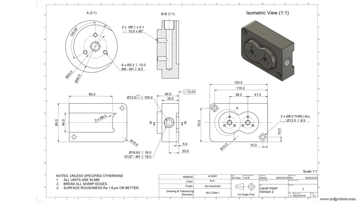
Screens marked “Actual screen” below are the software after this drawing was actually run. (App UI is in Traditional Chinese.)
01Drop in the drawing
Open the app, click New case, and you get a large drag-and-drop upload zone. Drag the file straight in, or click to choose it.
- Supported formats (in order of accuracy): DWG/DXF (vector, most accurate) > PDF > photo (PNG/JPG).
- Photos work too: a phone photo of a drawing is usable, but shadows, perspective and overlapping lines can make the AI misread through vs. blind holes — review photos by hand.
- Part number auto-filled: choosing a drawing fills the part number with the file name (editable), so even “just one drawing” gives a readable case name.
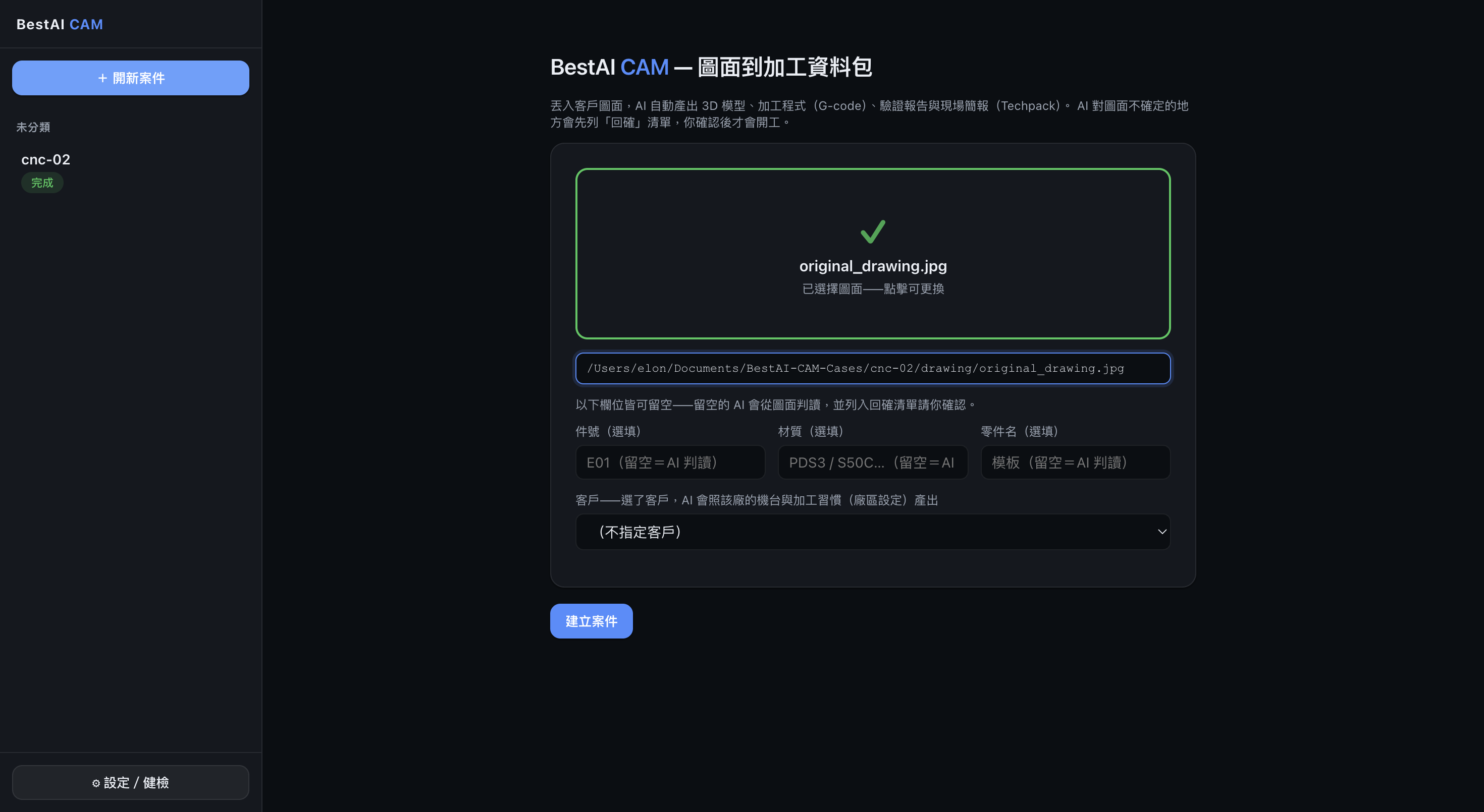
The new-case window: dropping a drawing shows a green check and the file name; part number / material / part name are all marked optional and a customer can be chosen; that blue Create case button at the bottom right is the one you press.
02Optional details (all can be blank)
Part number, material and part name are all optional. Leave them blank and the AI reads them from the drawing — for this drawing, it reads the material as aluminum 6061, the 120×70 outline, and each hole and thread.
- Pick a customer (recommended): once selected, the AI applies that shop's shop profile (machine list, controller, max spindle speed, zeroing habits), so the G-code and tool list match your machines.
- No customer is fine too: choose “No customer” to use the house defaults, or “New customer” with 3 quick questions (name / NDA / whether they use Mastercam).
03Press Create case — that's the button
As long as a drawing is attached, Create case is clickable. The moment you press it, the AI starts building — no further commands from you. This one action kicks off the whole automatic chain that follows.
What happens behind the scenes?
The app creates a “case = folder”, drives the local AI engine, and produces the package step by step following your shop's settings — all on your own computer.
04Watch the AI build live
A stage bar at the top lights up and advances in real time; the timeline beside it shows what the AI is doing at each step and which files it produced. You don't operate anything — just watch it run. The nine stages, in order:
| Stage | What this step does | Output |
|---|---|---|
| ① Setup & shop rules | Create the case folder, read in the drawing and your shop settings | Drawing |
| ② Read & plan | The AI reads the drawing and plans the work steps ahead | Work plan |
| ③ 3D modeling | Build the part into a 3D solid model from the drawing | 3D model (STL) |
| ④ Verify & measure | AI self-check: measure the 3D model and compare against the drawing | Verification & 3D measurement |
| ⑤ G-code | Generate the machining program for your machines and tool library | G-code & tool list |
| ⑥ Techpack | Produce a shop-floor instruction deck (PPT/PDF) | Techpack |
| ⑦ Cutting simulation | Produce a 3D animation of the machining you can rotate with the mouse | Cutting simulation |
| ⑧ Mastercam (optional) | Only if the customer uses it: produce a Mastercam import package | Mastercam package |
| ⑨ Delivery | Assemble an overview report and deliver the whole case | Overview README |
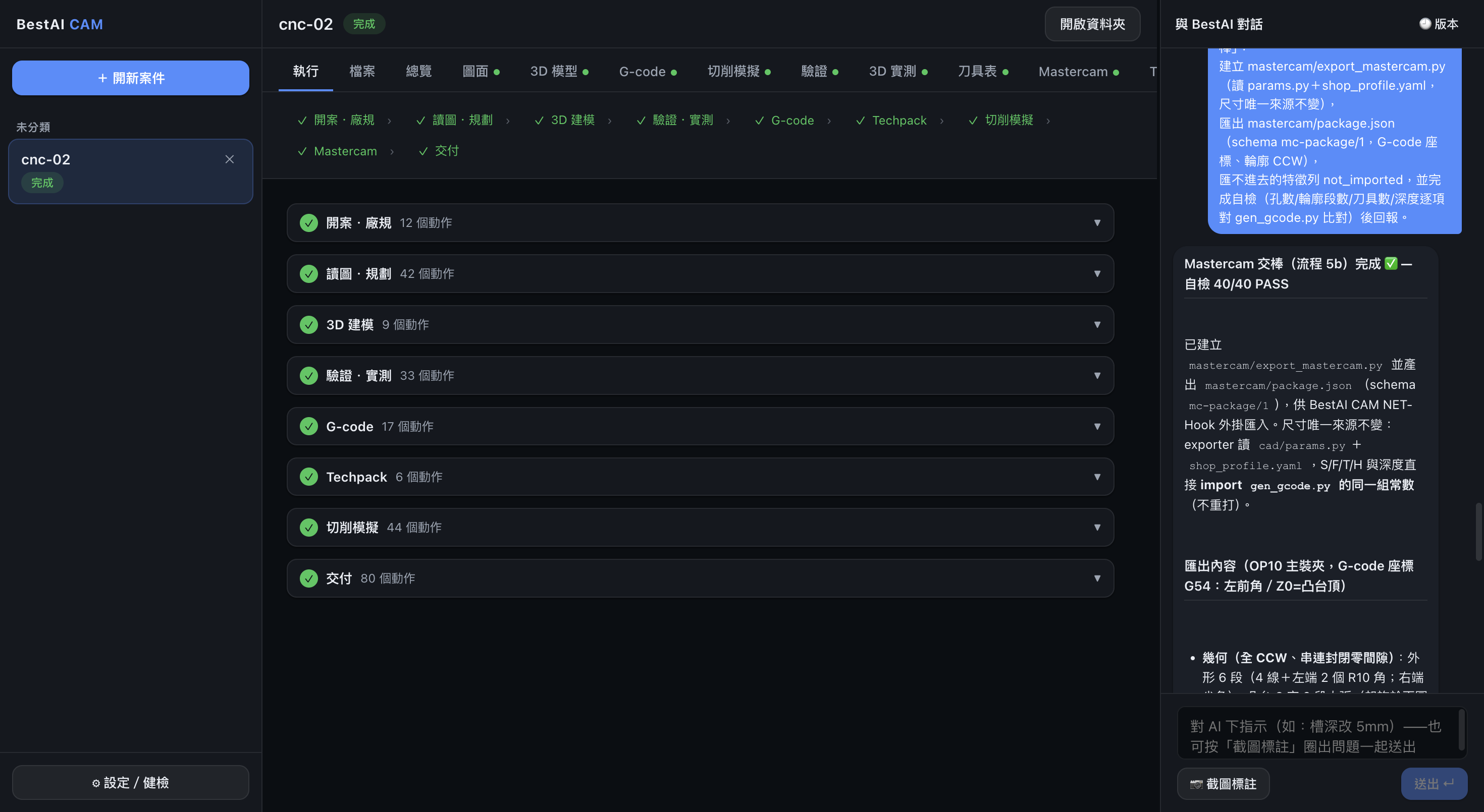
The run view during / after building: the nine-stage bar lights green one by one, the timeline shows how many actions each stage took (read & plan 42, cutting simulation 44…), and the chat panel on the right is the AI's closing summary each round.
05Confirm the AI's assumed dimensions
This is the most important step, and the heart of “AI accelerates, the professional makes the final call.” Anything not clearly marked on the drawing that the AI assumed (ASSUMED) is pulled out onto confirmation cards for you to confirm.
- Until you confirm, the case is not finalized for machining — a reminder stays on every tab.
- Confirm item by item, or accept the assumed values in one click; the AI then continues and finalizes the package.
- The judgment always stays with you: the AI lays out the basis for each assumption, and you only review and sign off.
06Browse the full results by tab
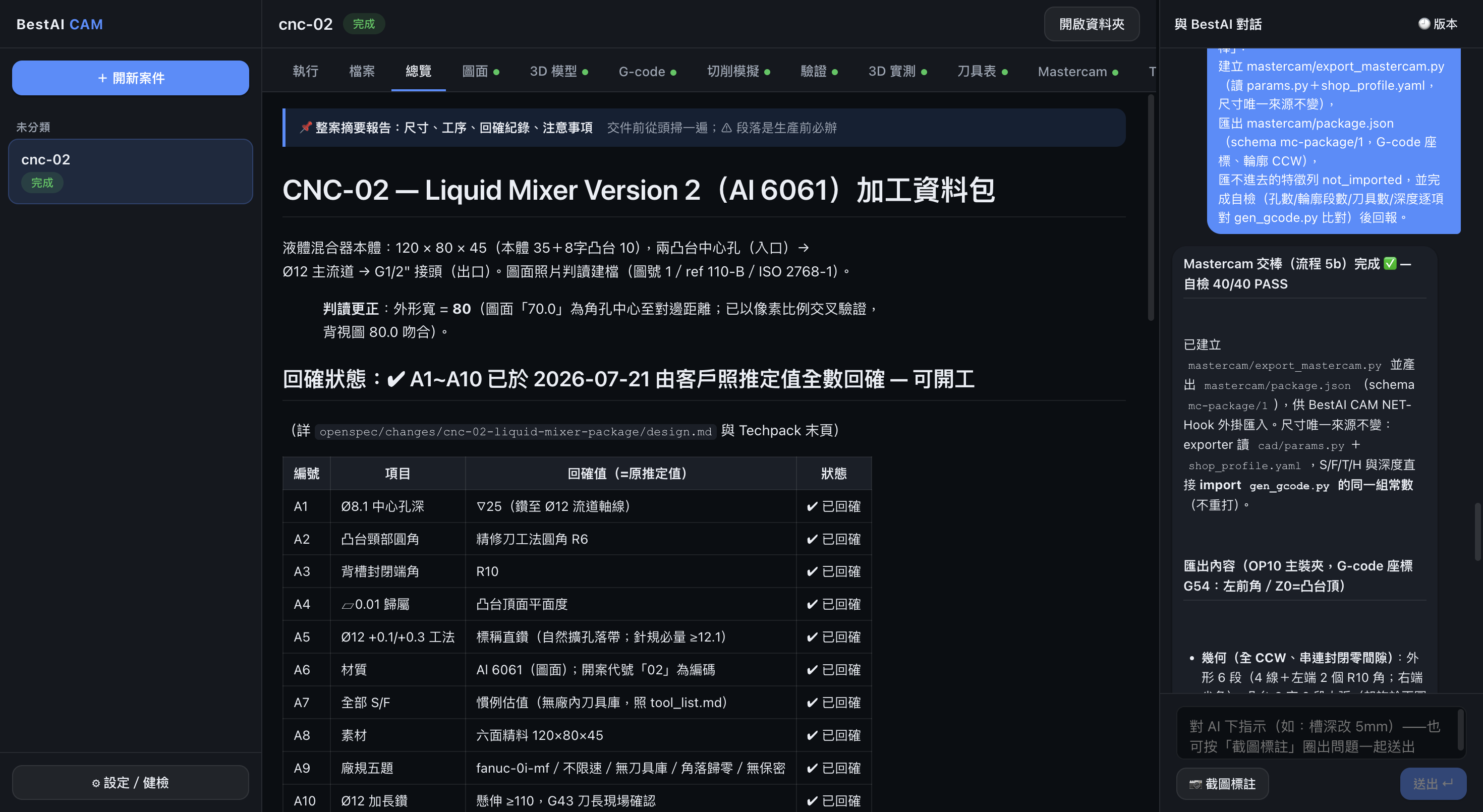
When building finishes, switch to the package portal and browse each output by tab. Tabs with no output are dimmed, so progress is obvious at a glance.
- Overview — the whole-case report and key summary.
- Drawing — the original drawing (DXF can be zoomed and panned in-app).
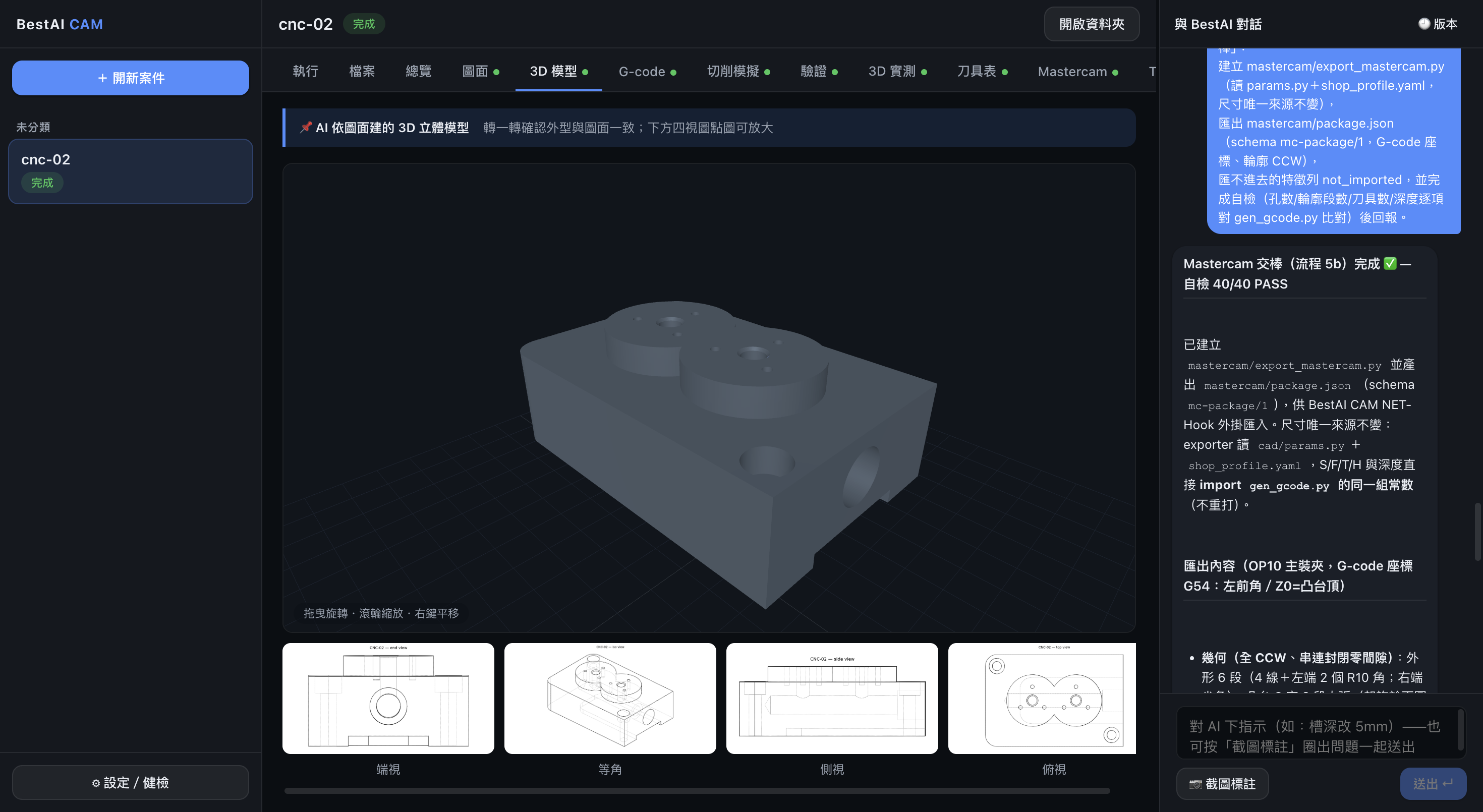
- 3D model — a solid model you rotate with the mouse.
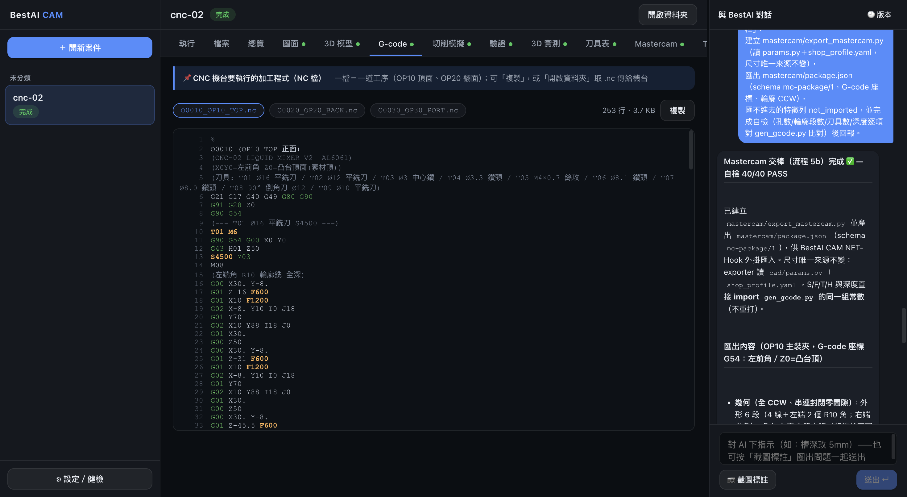
- G-code — the machining program, with line numbers, syntax coloring, copy and stats.
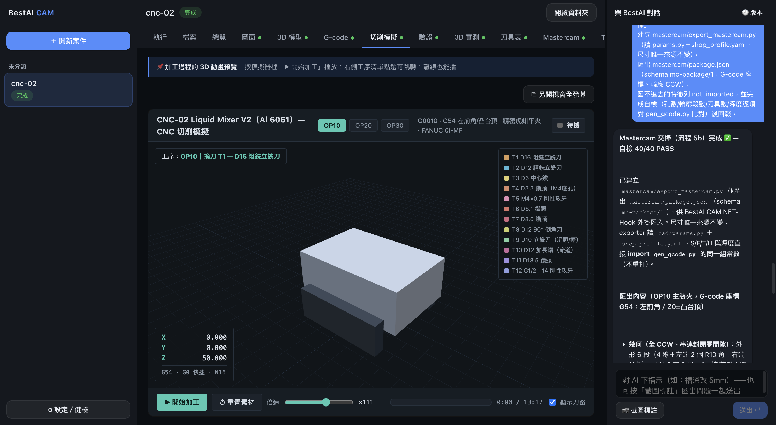
- Cutting simulation — a 3D animation of the machining.
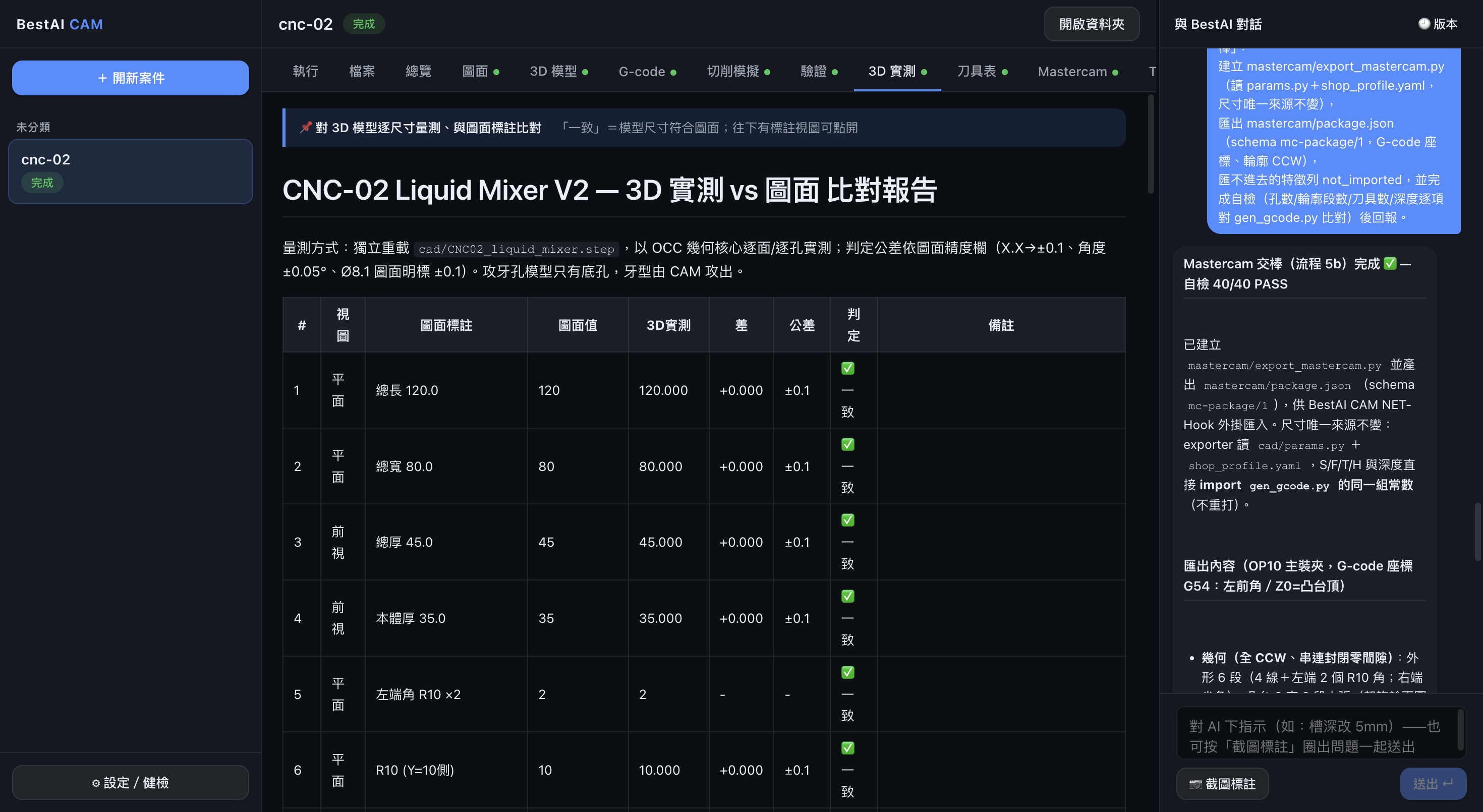
- Verification / 3D measurement — the AI measures the 3D model and compares it to the drawing dimensions item by item.
- Tool list — the tool list matched to your shop's tool library.
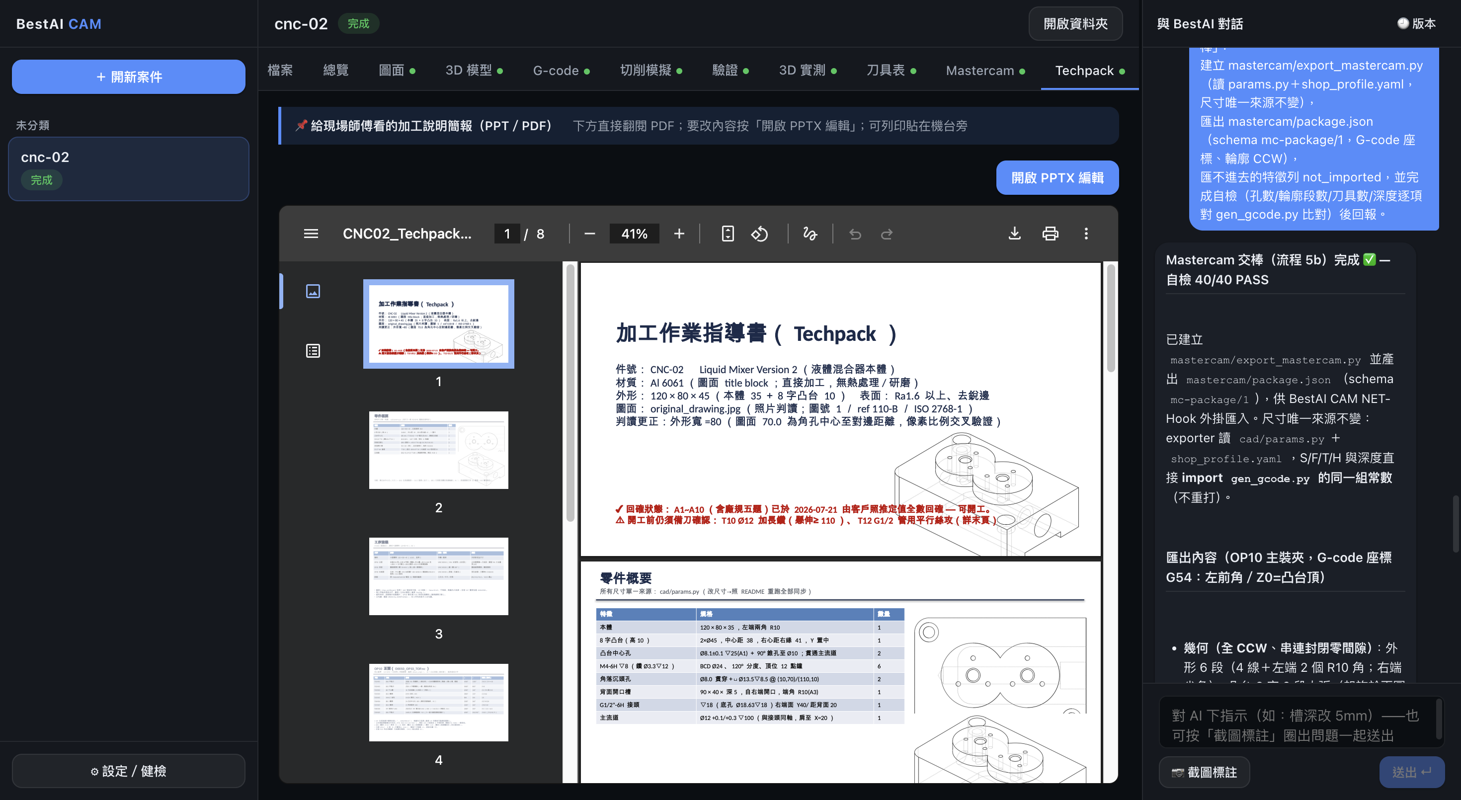
- Techpack — the shop-floor instruction deck.
ACTUAL SCREEN Here are the real tabs for this example (the liquid mixer) once finished:
✓In one sentence
Drop in a drawing → press Create case → watch it run → confirm the assumed dimensions → browse the results by tab. The modeling, programming, simulation and verification in between are all automatic; you keep the one thing that matters most: the final judgment.
Want to run it on your own drawing?
Leave your details and we'll arrange a live demo or pilot — on your machines and tool library, with your real drawings.
Client login See training courses