WORKHOLDING & FIXTURE DESIGN
Workholding & Fixture Design Basics: How Clamping Decides Accuracy and Efficiency
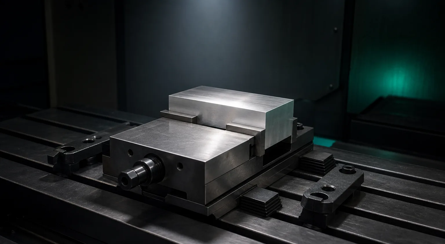
01Why workholding decides accuracy: locating datums and six-point location
Classic manufacturing-engineering texts say it again and again: machining accuracy depends on the whole "machine–tool–fixture–part" system, not any single link; how the part is located and clamped in the fixture sets the reference starting point for every dimension that follows (Kalpakjian & Schmid, 2020)[1]. Put another way, the locating datum is the origin of every dimension on the drawing — get the datum wrong and every dimension goes wrong with it.
The first problem workholding has to solve is "location": giving the part a unique, repeatable position in space. Any rigid body has six degrees of freedom (translation along the X, Y, Z axes, and rotation about each of them), and to fully fix the part you must constrain those six one by one — this is the six-point location principle. In practice a "3-2-1" arrangement is common:
- Primary locating face (3 points): seat the largest, flattest face against three locating points, constraining one translation and two rotations;
- Secondary locating face (2 points): rest against two points on the side, constraining one translation and one rotation;
- Tertiary locating face (1 point): the last point constrains the one remaining translation.
Done well, the part has only one stable position when set down, which is what gives part-to-part repeatability. If there are more locating points than needed (over-location), the part warps and builds internal stress because it can't seat on all points at once; if fewer than needed (under-location), the part shifts under cutting force and dimensions drift. That's why "finish the datum face first, then use it to locate" is a rule of thumb: using a rough, uneven stock face as the datum pours locating error straight into the finished part.
02Common workholding methods and where each fits
There is no "best" workholding method, only the one "best suited to this part and this batch." The table below lays out the four workholding families common in CNC milling and where each fits:
| Method | Suited to | Strengths | Watch out for |
|---|---|---|---|
| Precision flat-jaw vise | Square, rigid blocks and plate stock | Fast to set up, good repeatability, highly versatile | Needs flat clamping faces; thin parts get marred or deformed; large overhang invites chatter |
| Vacuum chuck / vacuum plate | Thin plates, large flat panels, finished faces you don't want to mar | Even loading, no clamp marks, whole sheet held at once | Needs a flat sealing surface; holding force is limited and lets go under heavy cuts or deep engagement |
| Dedicated fixture plate (custom tooling) | Irregular parts, multiple parts at once, a recurring flip datum | Fast setup, consistent datum, good for batches and flips | Design and build carry upfront cost, amortized over the batch |
| Four-jaw independent / three-jaw self-centering chuck | Round, rotational, eccentric parts | Four-jaw dials in eccentricity; three-jaw self-centers fast | Four-jaw needs indicating by hand and eats time; clamping a round face needs soft jaws to prevent marring |
The logic of the choice runs roughly: part shape screens out the unsuitable methods first (round parts are hard to hold in a vise, thin plates shouldn't be clamped hard), rigidity and surface decide the form of clamping force (go vacuum or soft jaws if you can't risk marring), and batch size then decides whether to build dedicated tooling for it. The next section digs into that batch-size line.
03Flips and re-fixturing: where the error comes from
Whenever one setup can't finish every feature, you have to flip or re-fixture — and every re-fixturing is a fresh source of locating error. Three common sources:
- Datum mismatch: if the second setup changes the locating datum, the first and second faces get measured from different origins, and their relative position (concentricity, symmetry) no longer lines up. The fix is to share one datum across both setups — for example keep the same reference edges, or machine a set of process holes / locating holes first and return to the same datum with locating pins after the flip.
- Clamping deformation: if the clamping point on the flip presses on an unsupported thin wall, the part is clamped slightly out of shape, and once machining is done and it's released it springs back, and the dimension is off.
- Chip and burr interference: a burr or leftover chip from the first face wedged under the second setup's locating face lifts the part a fraction, creating an invisible locating offset. Deburring and cleaning the locating face before the flip is fundamental.
Seen at the system level, re-fixturing error is essentially a process-planning problem: how you split the operations, choose the shared datum, and sequence the flips all accumulate or cancel error (Chryssolouris, 2006)[2]. Good fixture design is often a balance between "keeping the number of flips to a minimum" and "making every flip return to the same datum."
04Fixture amortization: how batch size changes the decision
Whether to build dedicated tooling for a part is a cost question. Dedicated tooling can sharply cut per-part setup time, stabilize the datum, and support multiple parts at once, but it carries its own upfront design and build cost. That cost has to be amortized over volume — manufacturing-systems theory classes it as the textbook fixed-versus-variable-cost trade-off: the fixture is a one-time fixed cost, and the amount charged to each part falls as the batch grows (Chryssolouris, 2006)[2].
An intuitive framework (using situations common in the trade as examples, not a specific quote):
- One-off / prototype: amortizing tooling doesn't pay; favor a general vise plus indicating, and keep cost in setup labor rather than tooling fabrication;
- Low-to-mid batch: consider modular fixturing or a simple fixture plate, trading a lower cost for repeatability;
- Steady batch / repeat orders: the per-part amortized cost of dedicated tooling is already low, and the setup time saved plus the yield gain usually recover the upfront investment quickly.
It's worth noting that for high-mix, low-volume job shops, the real cost driver is often not the fixture itself but the prep hours of re-planning workholding and programming every time the part changes. That's exactly the value of digitizing and making the machining-prep flow reusable — for more on the programming cost of prototypes and small batches, see the related articles in this column.
05Standardizing and passing on workholding knowledge
How the workholding scheme is set, how the datum is chosen, how the flip sequence is ordered — these calls lean heavily on a veteran's experience and are rarely written down. Automation and computer-integrated-manufacturing literature has long noted that if process and tooling knowledge can't be standardized and structurally preserved, staff turnover causes quality swings — one of the hardest thresholds a shop floor faces on the road to automation (Groover, 2019)[3].
A workable approach is to distill workholding knowledge into rules and templates the shop can look up:
- Locating-datum standards: which datum faces / process holes go with which class of part, written into an SOP rather than passed on by word of mouth;
- Fixture library and clamping parameters: catalog the specs and suitable parts for existing fixture plates, soft jaws and clamps, so the next selection has something to go on;
- Flip-operation templates: preserve the flip sequences and shared-datum methods that worked, as a starting point for similar parts.
Once this knowledge becomes searchable data, AI has boundaries to follow — it doesn't invent a clamping strategy from thin air, but makes suggestions within the shop's existing fixture library and datum standards, for staff to confirm. That's exactly the product-capability boundary the next section covers.
06Fixture-interference checks in AI simulation
Of the mistakes workholding produces, one class can be caught in simulation before the machine runs, and another can't — drawing the line matters.
What simulation can catch: geometric interference and collision. In the 3D cutting-simulation stage, once the geometry of the fixture, fixture plate, clamps and locating pins is placed into the scene, the system checks, segment by segment along the toolpath, for interference between the tool shank, spindle face and workholding, and flags travel-limit overruns. This effectively intercepts the most common workholding accident — "the toolpath itself is fine, but it hits a clamp during a rapid move." Paired with an independent AI cross-checking 3D-model dimensions against the 2D drawing, it can also catch, at the modeling stage, dimension offsets caused by differing datum interpretations.
What simulation does not claim to replace: physical judgment. Whether clamping rigidity is sufficient, whether the force deforms a thin part, how the real stock's stock allowance is distributed, the dynamic rigidity of the machine and fixture — these judgments involve cutting mechanics and shop-floor conditions and remain the final call of on-site professionals. AI's job is to nail the checks that can be made geometric and rule-based, and warn early; whether the part gets deformed by clamping, whether this datum fits the assembly intent, the master decides.
07FAQ
What is the "six-point location principle" in workholding?
A rigid body has six degrees of freedom in space (three translations, three rotations). Six-point location uses six sensibly placed points to constrain those six one by one, giving the part a unique, repeatable position — commonly a "3-2-1" arrangement. Too many locating points cause over-location and warping; too few cause under-location and shifting under the cut.
How do I choose between a vise, vacuum chuck, fixture plate and four-jaw chuck?
Look at shape and rigidity first: square, rigid parts use a precision vise; thin plates or finished faces you don't want to mar use a vacuum chuck; irregular parts, multiple parts at once, or a recurring flip datum use a dedicated fixture plate; round, eccentric parts use a four-jaw to indicate, regular round parts a self-centering three-jaw. Then let batch size decide whether to invest in dedicated tooling.
Why don't the two sides line up after a flip operation?
A flip is a second setup and introduces fresh error: datum mismatch, clamping deformation, and chips lifting the part all throw the relative position of the two faces off. The fix is to design a shared locating datum (the same reference edges or process holes plus locating pins), and confirm the post-flip coordinates and interference in simulation before the machine runs.
Can AI help check whether the fixture will crash the tool?
Yes, during the pre-machining 3D cutting simulation. With the fixture, fixture plate and clamp geometry placed in the simulation, the system checks the tool shank, spindle and workholding for interference along the toolpath and flags travel-limit overruns, catching the "path is fine but it hits a clamp" accident. But whether clamping rigidity is sufficient and whether it deforms the part still needs judgment from shop-floor professionals.
We'll let you know when new articles and video briefs go live — no inbox flooding, one-click unsubscribe. (newsletter in Chinese)
READY FOR A CONTROLLED PILOT?
Take one real part and lay out the workholding risk before the machine runs
From locating datums and flip operations to fixture-interference checks, we help turn your shop's workholding knowledge into boundaries AI can follow, and warn early in simulation.
Contact an onboarding advisor Training coursesFurther reading: Five-axis machining and AI · The complete guide to CNC auto-programming: from 2D drawing to verifiable G-code · Crash prevention and cutting simulation
08References
- Kalpakjian, S., & Schmid, S. R. (2020). Manufacturing Engineering and Technology (8th ed.). Pearson.
- Chryssolouris, G. (2006). Manufacturing Systems: Theory and Practice (2nd ed.). Springer.
- Groover, M. P. (2019). Automation, Production Systems, and Computer-Integrated Manufacturing (5th ed.). Pearson.