FIVE-AXIS & MULTI-FACE MACHINING
Can a 3-Axis Machine Make a 5-Axis Part? The Real Limits of Flip Machining, 3+2, and AI Face-Change Hints
01What is five-axis machining? The difference between 3-axis, 3+2, and simultaneous five-axis
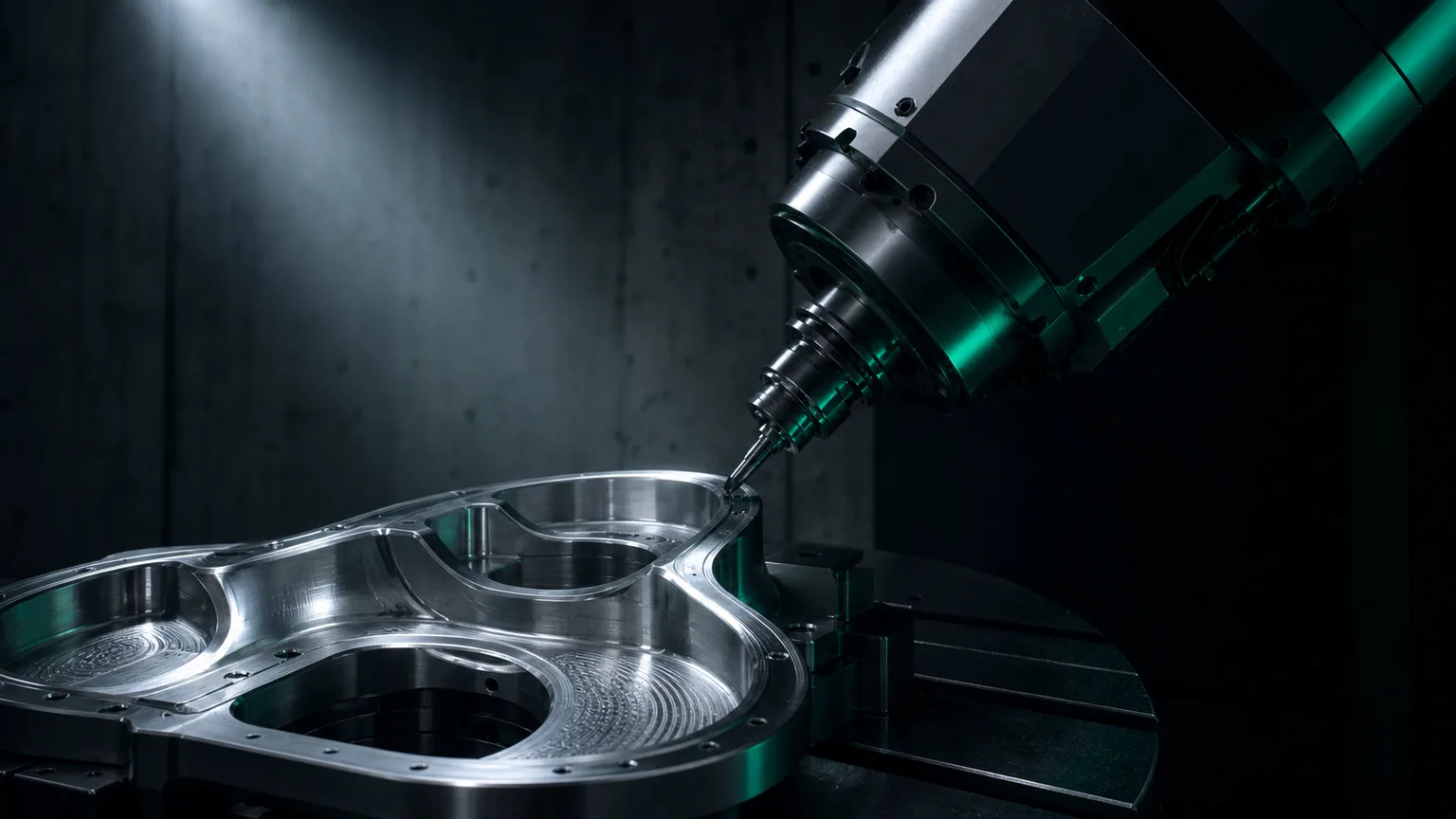
Five-axis machining means that on top of the X, Y, and Z linear axes, the machine adds two rotary axes (commonly any two of A/B/C), so the tool or workpiece can change relative angle while cutting. Its value is that "one setup can machine several faces," reducing the positioning error caused by re-fixturing and letting the tool cut complex surfaces at a better angle. Manufacturing-engineering textbooks also note that a substantial share of machining error comes from multiple setups and datum transfers, so reducing the number of setups is itself an important way to improve accuracy (Kalpakjian & Schmid, 2020)[1].
But "five-axis" actually has two very different uses; separate them first so you don't buy the wrong machine or quote the wrong price:
- 3+2 indexed machining (positional / indexed five-axis): first rotate the two rotary axes to an angle and lock them, then machine that face in 3-axis mode; re-index once when changing face. It is essentially "3-axis machining at multiple angles."
- Simultaneous five-axis: all five axes move continuously at the same time during cutting, with the tool-axis angle changing in real time to follow the surface — used for impellers, blisks, turbine blades, and other continuous free-form surfaces.
The key idea is: most parts need "several faces," not "a surface whose angle changes continuously." Recognize this and many jobs that "supposedly need five-axis" turn out to have a more cost-effective path.
02Can a 3-axis machine make a "5-axis part"? What flip machining can and can't do
The answer is: conditionally, yes. If a part just has features on all six faces but no continuously tilting surface running between those faces, a 3-axis machine can often finish it face by face through flip machining (re-fixturing and turning a new face up to machine it). This is exactly what many small and mid-size job shops in Taiwan have done for years — using one 3-axis machine, relying on fixtures and multiple setups to make multi-face parts.
The line between what works and what doesn't is roughly this:
| Part characteristic | Feasibility of 3-axis flip machining |
|---|---|
| Holes, slots, and pockets on several orthogonal faces | Feasible; machine face by face with flips — the key is datum and fixture planning |
| Features on a fixed inclined face | Can be done with an angle fixture or indexing table, then machined in 3-axis (close to the 3+2 idea) |
| Continuously varying free-form surfaces (impellers, etc.) | Not feasible; requires simultaneous five-axis to control the tool axis continuously |
| Deep cavities and inclined cuts where the tool must clear interference | Limited; the fixed 3-axis tool axis raises reach and tool-length problems |
Watch the cost: the more flips, the higher the accumulated positioning error and cycle time. Every re-fixture requires re-aligning the datum, and even a slight offset shows up in the position tolerance between faces. Authoritative texts on cutting mechanics and machine-tool design also warn that fixturing rigidity and positioning stability directly affect vibration and dimensional accuracy during cutting, and that looseness or excessive overhang amplifies error (Altintas, 2012)[2]. So for multi-face parts on a 3-axis machine, success or failure often lies not in the machine but in datum planning and fixture design.
033+2 indexed machining: the practical answer for most multi-face parts
When a shop has a machine with a rotary axis (for example, a 4th axis / indexing table, or a real five-axis machine), 3+2 indexed machining is usually the most practical answer for multi-face parts. The method rotates the workpiece to an angle, locks the rotary axis, and then machines that face in 3-axis mode; when the next angle is needed, it re-indexes.
Compared with simultaneous five-axis, 3+2 has several floor-level advantages:
- Better rigidity: the rotary axis is locked during cutting, giving the stability of 3-axis machining — suitable for roughing that removes large amounts of material.
- Simpler programming and verification: each machining face is one segment of a 3-axis program, so paths are intuitive, simulation is easy, and the error rate is lower than continuous five-axis interpolation.
- Fewer setups: multiple angles are done within one setup, removing the re-alignment error source of pure 3-axis flipping — echoing the "fewer setups, less error" principle[1].
What genuinely calls for simultaneous five-axis is when the tool axis must "change angle continuously along the surface" — for example, blade surfaces or complex contours that need to be flank-milled in one pass. Forcing a job that 3+2 could solve onto simultaneous five-axis only adds programming and collision risk, and doesn't pay off. Choosing the right machining strategy matters more than buying the most expensive machine.
04How AI suggests "face-change logic": from machining features to machining-face planning
One of the most demanding parts of multi-face machining is deciding "which features go on the same machining face, in what order the faces are machined, and how the datums are set." This step used to rely heavily on a veteran machinist's experience. AI-assisted programming can add value here: once the system reads the machining features on the drawing, it can suggest a reasonable face-change draft using standard five-axis / multi-face machining logic.
Concretely, what AI can do is:
- Grouping features by face: based on the orientation of each feature, suggest which holes, slots, and faces belong to the same machining face, reducing unnecessary flips.
- Machining-face order hints: following the general rules of "rough before finish, datum face before dependent face," draft the order of the machining faces.
- Initial datum and reach assessment: flag the datum source for each face and possible tool-reach problems, so the engineer can adjust fixtures early.
- Cross-checking against the 3D drawing: an independent AI pass compares the generated model's dimensions against the original drawing annotations one by one and proactively flags anomalies — the same read-the-drawing and cross-verification mechanism described in the complete guide to CNC automated programming.
05Pin-alignment and manual re-fixture measurement: why the machinist is still a critical gate
When a 3-axis machine makes multi-face parts, or when 3+2 machining is used, the accuracy is often held by a few floor-level steps that "can't be handed to AI":
- Pin-alignment: after flipping or changing the fixture, use a pin or dial indicator to re-find the datum and confirm the workpiece's real position in the machine coordinate system. This involves the actual fixture state and hands-on feel, and is the core of alignment.
- Real measurement after a manual re-fixture: after changing face, first measure the key dimensions and positions to confirm the datum transfer from the previous face to this one has no offset, then continue machining.
- Fixturing and on-the-spot workarounds: for thin-wall, easily deformed, or overhanging parts, the machinist adjusts clamping force, shims, and machining order on the spot — judgments that come from real experience with the material and the machine.
The reason it can't all be handed to software is that the cutting process itself is a system of interacting forces, vibration, and thermal deformation, and the actual state shifts with tool wear, clamping rigidity, and workpiece material (Altintas, 2012)[2]. AI can suggest "how the face should change," but whether "this particular setup is actually aligned" can only be confirmed by on-the-spot measurement and alignment. The right division of labor is: AI reads the drawing, groups faces, generates code, and cross-verifies; the machinist handles datum alignment, re-fixture measurement, and final sign-off.
06Collision checks before the job runs: why multi-face machining needs simulation even more
The more faces and the trickier the angles, the higher the risk of collision and gouging: the holder, fixture, rotary table, and workpiece can all interfere with each other. This is why multi-face and five-axis machining need verification more than single-face 3-axis machining. A CIRP (International Academy for Production Engineering) review notes that virtual machining can simulate material removal before the job runs and predict collisions and gouges, making it a key means of lowering trial-cut costs and shortening implementation time (Altintas et al., 2014)[3].
For multi-face / 3+2 machining, the recommended pre-run verification includes:
- Path simulation for each machining face: check face by face for gouges, remaining stock, and travel overruns.
- Tool and fixture interference check: pay special attention to collisions between the holder and the fixture or rotary table after an angle change.
- Reviewing the face-change order for soundness: confirm the datum face is machined first and dependent faces afterward, avoiding loss of the datum.
For the complete approach to cutting simulation and crash prevention, read on in What Does One CNC Crash Really Cost? Cutting Simulation and AI Verification; for how to set the speed, feed, and depth of cut for each face, see How to Set Cutting Parameters: The Theory Behind Speed, Feed, and Depth of Cut, and AI Assistance. Doing these steps before the job runs is what keeps the risk of multi-face machining ahead of the trial cut.
07FAQ
Can a 3-axis machine really make a 5-axis part?
It depends which kind of "5-axis part." If the part just needs machining on several faces, with no continuously tilting surface between them, a 3-axis machine can often finish it face by face with flip machining — it just adds more face-change and alignment steps. Truly complex surfaces requiring the tool axis to change angle continuously (impellers, blisks) do require a simultaneous five-axis machine. So "3-axis making a 5-axis part" holds true conditionally; the deciding factors are geometric complexity and accuracy requirements.
What is the difference between 3+2 machining and simultaneous five-axis?
3+2 first rotates the workpiece or tool to a fixed angle, locks the two rotary axes, then machines that face in 3-axis; each angle change is re-indexed once. Simultaneous five-axis has all five axes moving continuously during cutting, with the tool axis changing in real time to follow the surface. Most multi-face parts can be finished with 3+2, which is also more rigid; only continuous free-form surfaces truly require simultaneous five-axis.
Can AI plan five-axis face changes automatically?
AI can suggest "standard face-change logic" from drawing features — which features are on the same machining face, a recommended machining-face order, and rough datum planning — so engineers don't start from scratch. But pin-alignment, real measurement after a manual re-fixture, fixturing, and on-the-spot workarounds remain the shop-floor machinist's job. AI provides a reasonable draft and cross-check; it does not replace setup and alignment judgment.
Can a five-axis or multi-face program be run straight on the machine?
Not recommended. Five-axis and multi-face machining make the tool, holder, fixture, and rotary axes more prone to collision and gouging, so the program should first pass a cutting simulation that checks paths and interference, and a senior technician should confirm the setup, datums, and face-change order before it runs. Virtual machining verification is the key step that lowers the risk of trial cuts and crashes.
Get notified when new articles and video briefings go live — no inbox spam, one-click unsubscribe. (newsletter in Chinese)
READY FOR A CONTROLLED PILOT?
Hand a multi-face drawing to an AI that understands machining logic for a first pass
From grouping features by face and machining-face order to collision simulation, we help you use AI to accelerate the face-change draft, then have the machinist align and sign off — finding the most cost-effective machining strategy.
Contact an implementation consultant Training courses08References
- Kalpakjian, S., & Schmid, S. R. (2020). Manufacturing Engineering and Technology (8th ed.). Pearson.
- Altintas, Y. (2012). Manufacturing Automation: Metal Cutting Mechanics, Machine Tool Vibrations, and CNC Design (2nd ed.). Cambridge University Press.
- Altintas, Y., Kersting, P., Biermann, D., Budak, E., Denkena, B., & Lazoglu, I. (2014). Virtual process systems for part machining operations. CIRP Annals, 63(2), 585–605.