NON-FERROUS & ENGINEERING PLASTICS
Milling Copper, POM and Acrylic: A Guide to Non-Ferrous Metals and Engineering Plastics
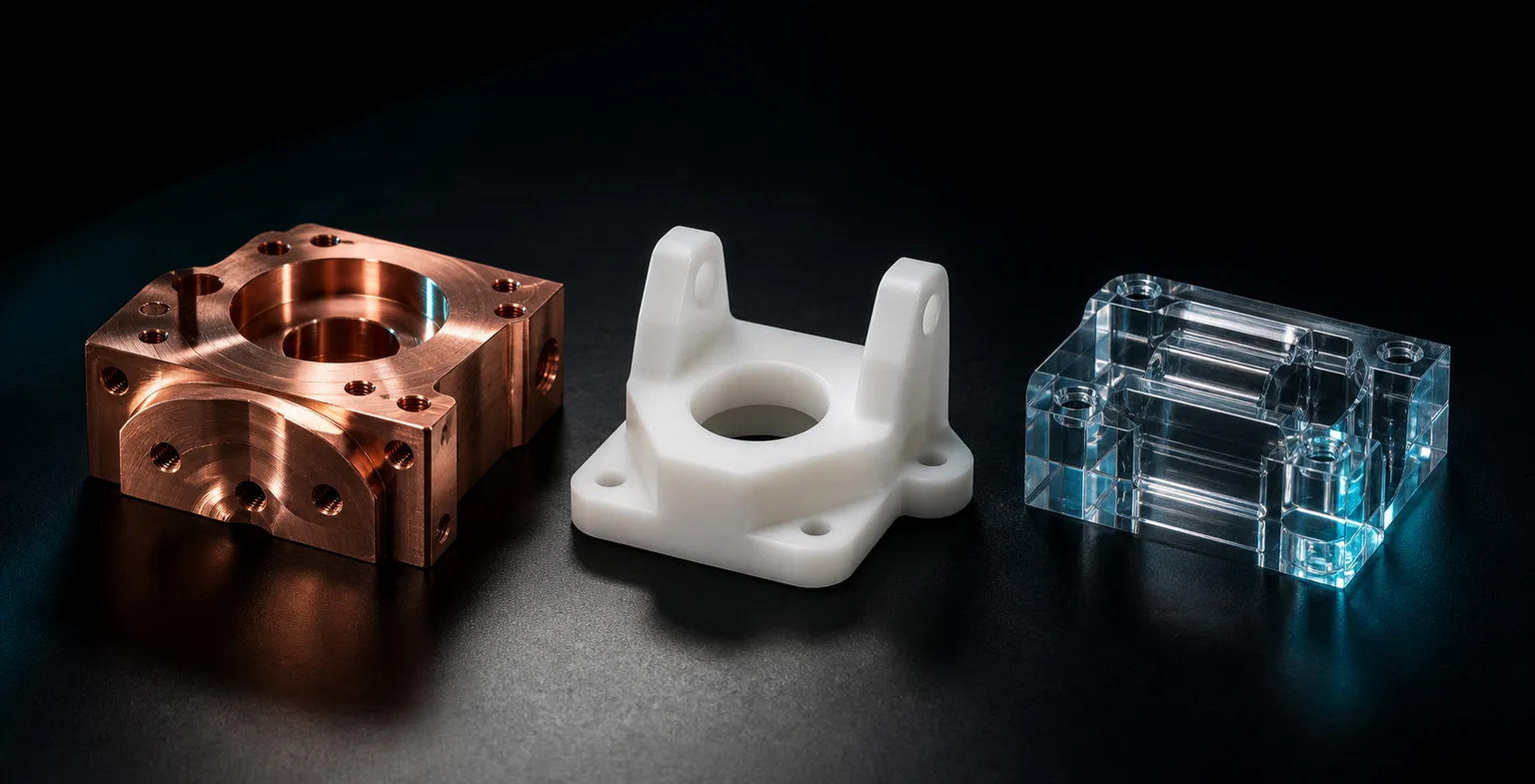
01Why you can't machine soft-material parts with a metal-part mindset
Non-ferrous metals and engineering plastics are often filed under "easy to cut," and that's where the misunderstanding begins. Manufacturing-engineering textbooks note that a material's mechanical and thermophysical properties — hardness, toughness, thermal conductivity, thermal expansion — directly govern chip formation, built-up-edge tendency and surface integrity during cutting, and different materials call for different tool geometry and cutting strategies (Kalpakjian & Schmid, 2020)[1]. Copper is too sticky, plastic too soft and too heat-sensitive — neither is a problem you solve by just "cranking up the speed and pushing the feed."
More to the point, "good machinability" for these materials often means low cutting resistance and long tool life — it does not mean it's easy to hit dimensional accuracy and a clean appearance. The real difficulty concentrates in burrs, cracking, thermal distortion and tolerance stability. Below we break down the temperament and countermeasures of four common soft materials one by one; all are qualitative principles, and actual parameters should still follow the shop's tool library and test-cut results.
02Copper and copper alloys: gumming, built-up edge and burrs
Pure copper (electrolytic, oxygen-free) is extremely ductile and soft, the first choice for electrical and thermal-conduction parts — and also one of the materials most prone to "gumming the tool." During cutting the material tends to adhere to the cutting edge and form a built-up edge, dragging scratches across the surface and drifting the dimension, while hole edges and corners easily roll burrs. Textbooks class these highly ductile metals as having a marked tendency toward built-up edge and burrs, requiring a sharp edge and appropriate cutting conditions to suppress adhesion (Kalpakjian & Schmid, 2020)[1].
Practical countermeasures run in a few directions:
- Sharp tools, smooth chip evacuation: large chip flutes and a sharp edge reduce material adhesion and built-up edge; a dull tool degrades burrs rapidly on copper.
- Coolant and parameters to suppress built-up edge: appropriate cooling and lubrication plus cutting speed keep built-up-edge formation down and stabilize surface quality.
- Schedule deburring into the process: burrs on copper parts are all but inevitable; design in a deburring operation rather than expecting a one-pass finish.
- Use an alloy when you can: unless strict electrical/thermal conduction is required, a better-machining copper alloy such as brass is far less hassle than pure copper.
03POM: a great, dimensionally stable material undone by thermal expansion
POM (polyoxymethylene, also known as acetal or Delrin) is the model student of machinable engineering plastics: rigid, cutting smoothly, chipping into strands, relatively dimensionally stable — gears, sliders and bushings often specify it. But it has one property that trips people up: a coefficient of thermal expansion far higher than metal. Engineering plastics generally have large thermal expansion and low thermal conductivity, so cutting heat isn't easily carried away and the dimension shifts the moment the temperature changes (Kalpakjian & Schmid, 2020)[1].
That brings two practical problems. First, a part fresh off the machine is temporarily expanded by cutting heat, so a dimension measured while it's warm differs from the one after it cools back to room temperature — easily misjudged as out of spec or in spec. Second, the same POM part that measures good in an air-conditioned room can jam or slip in a hot environment. The fix: let the part return to room temperature before measuring, control cutting heat and evacuate chips reliably to avoid local softening, and factor the material's thermal expansion and contraction into the tolerance at specification and acceptance — rather than forcing a metal part's tight tolerance onto it. POM also has slight moisture absorption and internal-stress release; for thin or long parts you can rough mill, let it sit a while, then finish, to reduce distortion.
04Acrylic: the dilemma between cracking and gumming
Acrylic (PMMA) is chosen for its transparent appearance, and machining it pits two opposite enemies against each other: on one side cracking, on the other gumming. Acrylic is a brittle material, so too fast a feed or a dull tool chips and whitens the edge; but cranking the spindle speed up and slowing the feed just to avoid cracking raises the local temperature, making chips stick and the edge haze or even melt and re-adhere. This is the classic dilemma of brittle, heat-sensitive materials in cutting (Kalpakjian & Schmid, 2020)[1].
A workable approach is to strike a balance between a sharp dedicated tool, climb milling, reliable chip evacuation and controlled cutting heat, and to leave a light finishing pass on the edge. One point worth stressing to customers: a milled edge is not a polished edge. A glass-clear cut edge usually takes downstream mechanical or flame polishing; getting there with milling in one shot isn't realistic. Designs with too small an inside radius or too thin a wall sharply amplify the cracking risk, and such features are best discussed at the design stage.
05Phenolic: dust, wear and the trade-offs of insulating parts
Phenolic (phenol-formaldehyde resin, with a glass-fiber or cotton-fabric base) is common in insulating fixtures, terminal boards and heat-resistant gaskets. It doesn't gum the tool much when cut, but it brings two shop-floor headaches. First is dust: machining phenolic produces fine powder rather than strand chips, irritating to airways and equipment alike, and it needs good dust collection and protection. Second is tool wear: a composite base with glass fiber or filler has many hard points that abrade the tool far more than pure resin — a textbook hard-to-machine composite, with tool life and tool-change cadence both needing to be re-estimated (Kalpakjian & Schmid, 2020)[1].
As for countermeasures, dust collection and personnel protection come first; tools lean toward wear-resistant grades with a shorter tool-change cycle; the layered and insulating nature also makes machining in certain directions prone to delamination or edge chipping, which needs test cuts to confirm. Phenolic parts are mostly about insulation and heat resistance, and their dimensional tolerances are usually not as demanding as a metal part's — spelling out the functional requirements when placing the order is more pragmatic than chasing precision blindly.
06Realistic tolerance expectations for plastic parts
Applying a metal part's tolerance table straight to a plastic part is the most common source of quoting and acceptance disputes. Engineering plastics have large thermal expansion, low rigidity, and post-machining internal-stress release and moisture-driven changes — properties that make a plastic part's dimensional repeatability under the same operations inherently looser than a metal part's (Kalpakjian & Schmid, 2020)[1]. Forcing it down to a metal-grade tolerance costs slower machining, more part sorting and a higher quote, without necessarily buying a stable yield.
The sensible approach is to sort out which dimensions really matter. Tighten mating faces, shaft holes and locating faces a bit, loosen cosmetic faces and non-mating dimensions, and clearly note the measurement conditions (for example, at room temperature, measured after returning to temperature). Spelling out "where it must be precise and where it can be loose" often costs less than tightening the whole drawing uniformly and passes acceptance more easily. As for which dimensions are worth paying the price of high precision, see our overview of the accuracy-cost relationship.
07CNC prototyping or injection production?
A common fork for plastic parts is whether to cut them directly from plate or bar stock on CNC, or cut an injection mold for production. This is really a classic manufacturing-systems trade-off: different processes each have their own cost structure and suitable batch size, and the core of the choice is quantity, variability and lead time rather than unit cost alone (Chryssolouris, 2006)[2].
The decision can center on three questions:
- How many? A few to a few hundred, and CNC is usually the most economical; only at tens of thousands does injection's per-part cost advantage come into play.
- Is the design finalized? Parts still subject to revision are most flexible on CNC — revise the drawing and recut; once a hardened injection mold is cut, changing the design means a sizable mold-modification cost and time.
- How fast do you need it? CNC prototypes can be delivered for validation within days, while injection has to bear the mold-cutting cycle first.
Manufacturing-systems theory reminds us that the cost-optimal strategy is to treat different processes as a complementary set of capabilities and switch between them by batch size and life-cycle stage (Chryssolouris, 2006)[2]. In practice many products go exactly "CNC prototype to validate the design → transfer to injection production once finalized," a relay rather than an either/or. When structure still needs tweaking and assembly still needs validating before production, the CNC part is the most efficient waypoint.
08How AI drawing reading supports soft-material parts, and where the line is
The trouble with soft-material parts is usually not geometric complexity but the material's temperament and the sequencing of operations. What AI drawing reading helps with here is moving the prep stage earlier: from a 2D drawing (DWG preferred, PDF and photos as backup) it identifies hole positions, slots, thin walls and machining features and builds a 3D model, flagging before quoting the deep slots, thin walls and too-small inside radii most likely to cause trouble, so the engineer can discuss the design or operations with the customer sooner. When generating G-code, the AI writes the program to the shop's tool library, controller and travel/speed limits, and an independent second AI cross-checks the model against the original drawing's dimensions to reduce missed checks.
But the line is just as clear: material selection, cutting strategy, deburring and polishing operations, and the final call on plastic-part tolerances remain shop-floor expertise. Whether copper should switch to brass, whether an acrylic edge needs polishing, whether a POM part should wait to return to temperature before measuring — these decisions involve material experience and customer intent; AI puts the information on the table and speeds up interpretation, and staff make the call. This is exactly the human-in-the-loop division of labor: AI speeds up prep, the master keeps final judgment. To learn how AI drafts cutting parameters by material, see the related article.
09FAQ
Why do POM parts so often not fit during assembly?
POM is dimensionally stable and machines well, but its thermal expansion is far higher than metal, so a difference between the room temperature at measurement and the service temperature produces an offset. Cutting heat also expands the part temporarily, so the dimension off the machine and after returning to room temperature differ. Measure after it returns to temperature, and leave room for thermal expansion when specifying tolerances — don't force a metal part's tolerance onto a plastic part.
Why does milling acrylic crack or leave a hazy edge?
Acrylic is brittle; too fast a feed or a dull tool chips the edge, while too high a speed and poor chip evacuation raise the local temperature, making chips stick and the edge haze or even gum. The fix is a sharp dedicated tool, climb milling, controlled cutting heat and reliable chip evacuation, plus a light finishing pass. A clear polished edge usually takes downstream polishing or flame treatment, not milling in one shot.
Why does machining copper easily gum the tool and raise burrs?
Pure copper is soft and highly ductile, so it readily adheres to the edge, forming a built-up edge, and rolls burrs at hole edges and corners. The fix is a sharp tool with large chip flutes, coolant and parameters to suppress the built-up edge, and deburring scheduled into the process. If electrical/thermal conductivity isn't needed, switching to a better-machining copper alloy such as brass is far less hassle.
For a small prototype run, should I use CNC or go straight to an injection mold?
For a few to a few hundred plastic parts that need fast validation or may be revised, cutting directly on CNC is the most economical option — no mold cost and no mold lead time. Only at tens of thousands with a finalized design does injection's per-part cost drop low enough to amortize the mold. Prototypes, low volume and frequent revisions go CNC; high volume, finalized design and lowest unit cost go injection — the two are complementary.
We'll let you know when new articles and video briefs go live — no inbox flooding, one-click unsubscribe. (newsletter in Chinese)
MATERIAL-AWARE QUOTING
See a material's temperament clearly, before you quote
Whether it's burrs on copper, thermal distortion on POM or the cracking risk of acrylic, we help flag the machining challenges and realistic tolerances of soft-material parts right at the drawing-interpretation stage.
Contact an onboarding advisor Training courses← Back to the pillar article: how AI turns a 2D drawing into verifiable G-code
10References
- Kalpakjian, S., & Schmid, S. R. (2020). Manufacturing Engineering and Technology (8th ed.). Pearson.
- Chryssolouris, G. (2006). Manufacturing Systems: Theory and Practice (2nd ed.). Springer.