SCENARIO · MOLD & TOOLING
Mold & Tooling Machining: AI CAM in Practice for Deep Cavities, Corner-Clearing, and One-Off Custom Work
01What makes mold & tooling machining distinct
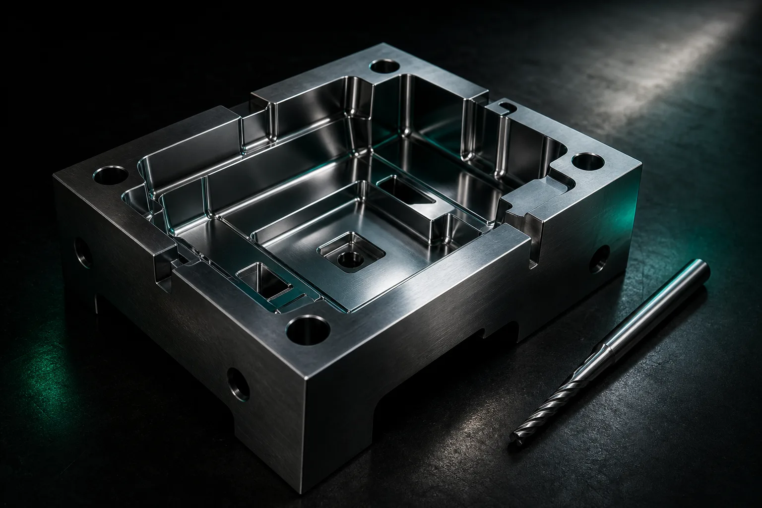
Mold machining and fixture CNC are among the most "one-and-done" work in the machine shop: injection-mold cores, stamping lower dies, inspection fixtures, assembly jigs — often just one of each is made, with no production run to spread the cost of trial and error. The machining characteristics of these parts come down to four points, each of which directly shapes programming and setup strategy.
- One-off custom, no room for trial and error: cores and fixtures are usually tailored to a product or workstation — one part, one blank. Scrap it and you write off the whole block of hard material plus the labor, with no second trial cut.
- Deep cavities, corner-clearing, and long tool reach: cavities are deep and corners are tight, often forcing long tools into the cavity. As reach grows, rigidity drops and vibration risk rises — the main threat to both precision and tool life.
- Hard-material finishing: mold steels are usually finish-machined only after heat treatment brings them to high hardness — difficult-to-cut work with a narrow tolerance window for cutting conditions. Textbooks list material and heat-treatment state as the primary variables in process planning[1].
- Frequent rework: post-tryout tuning, product changes, and local reinforcement send the same mold in and out of machining again and again. Each pass changes only a small area yet needs reprogramming, so the front-end rework is heavier than you'd expect.
02Why the pressure to get it right the first time is so high
Stack those characteristics together and the pain points a mold-and-fixture shop faces are, at their core, the concentrated amplification of three kinds of cost.
1. The pressure to get it right the first time. One-off, hard material, deep cavity — a slip at any single step (a misread dimension, a wrong tool-length setting, a poor plunge strategy) can scrap the entire core outright. With no production volume to absorb it, every part is effectively "first article is also last article," and the margin for error approaches zero.
2. Deep-cavity chatter and long tool reach. Deep-cavity work forces longer tools, and cutting stability depends on the dynamic rigidity of the tool–workpiece system; as reach increases and system rigidity falls, it easily slips into regenerative chatter — degrading tool marks, throwing off dimensions, even breaking tools. The authoritative texts on cutting mechanics and CNC design are explicit that feed, spindle speed, and depth of cut must be grounded in the mechanics and vibration behavior of the tool–workpiece system; otherwise you get poor precision at best and a broken tool or crashed machine at worst (Altintas, 2012)[2]. Deep-cavity corner-clearing is exactly where that rule is most easily broken.
3. High program-verification cost. Because you can't verify with a trial cut, the pre-machining checking burden on mold programs is unusually heavy: gouges, residual stock, fixture interference, and travel overruns all have to be confirmed by hand, over and over, inside the CAM system. Anomalies during machining are also hard to catch in real time — a CIRP review notes that although advanced machining monitoring (tool-wear, breakage, and chatter detection) is a major research focus, deploying it reliably on the shop floor still has hurdles (Teti et al., 2010)[4]. In other words, after-the-fact monitoring can't restore an already-gouged core; doing the verification before the machine runs is the real answer.
03Deep cavities and corner-clearing: how simulation-first prevents gouges and crashes
For work that "can't afford trial and error," the most effective countermeasure is to move the trial and error into the computer. A CIRP review notes that virtual machining can simulate material removal and predict collisions and gouges before the machine runs — a key means of cutting trial-cut costs and shortening ramp-up time (Altintas et al., 2014)[3]. In mold-and-fixture practice, AI CAM verification should cover two layers.
- Geometry / path verification: preview the deep-cavity plunge and corner-clearing paths with 3D cutting simulation, checking for gouges, residual-stock distribution, fixture interference, and travel overruns under long tool reach — stopping the crash on the screen rather than on the core.
- Dimensional cross-check (AI verifying AI): once the 3D model is generated, a second, independent AI compares the model's dimensions against the 2D drawing callouts one by one and actively flags anomalies, lowering the miss rate of manual review on one-off parts.
For the simulation to be trustworthy, the generation stage has to be tied to the shop's real conditions. A reliable AI CAM constrains itself with your dedicated tool library (codes, actual lengths, cutting parameters for the corresponding reach), the machine controller's dialect, and travel and spindle-speed ceilings, so the AI only picks tools that actually exist and suit that reach — not whatever it likes. For the full approach to crash prevention and simulation verification, see this blog's How cutting simulation and AI verification stop accidents before the machine runs.
04Frequent rework: AI drawing reading speeds up reprogramming and tool-library management
Rework is the front-end labor sink that mold shops find hardest to standardize. Post-tryout tuning often touches only a local area, yet it makes the engineer re-read the entire program. This is where AI drawing reading delivers clear value: from the updated 2D drawing (DWG first, PDF or photo as backup) it re-recognizes dimensions, hole positions, and machining features and refreshes the 3D model, so the engineer doesn't rebuild from scratch; a cross-checking AI then flags exactly what changed this time, focusing human effort on "are the method and tolerances right" rather than "did I read the drawing correctly."
The classic texts on automation and computer-integrated manufacturing have long stressed that when process knowledge lives only in a few people's heads and can't be documented, staff turnover causes quality to fluctuate (Groover, 2019)[5]. By accumulating a shop tool library and a history of successful programs, AI CAM is precisely a way to gradually structure know-how like "what parameters this long tool should use in this kind of deep cavity." Tool-library management matters most for deep cavities — if a long tool's actual stick-out and its corresponding conservative cutting parameters are all on file, AI generation and simulation can reference them consistently, avoiding crashes caused by a wrong tool-length setting. For how cutting parameters get constrained under shop conditions, see How AI gives cutting parameters within the shop's limits.
05Human-in-the-loop: the last gate for hard-material finishing
Molds and fixtures are one of the scenarios where you least want to hand the final call to AI. The following remain the domain of shop-floor expertise for now — AI provides the starting point, the master decides:
- the split between roughing and hard-material finishing, the stock-allowance strategy, and the clamping and re-fixturing sequence;
- on-the-spot tuning of depth of cut, spindle speed, and feed under long reach in deep cavities — whether it chatters is judged from tool marks, sound, and machine rigidity, a feel AI can hardly replace;
- the sequencing of mold-specific processes like electrodes, EDM, and grinding, and the final confirmation of tolerances, datums, and assembly intent.
The right division of labor is: AI handles drawing reading, modeling, code generation, and cross-checking to compress prep time; the shop-floor expert handles chatter control, hard-material finishing, and pre-run sign-off. For strategy choices on multi-axis deep cavities and complex surfaces, see Applying AI CAM to five-axis machining. With each doing what it does best, the overall risk on a one-off mold ends up lower than with either all-manual or all-automatic.
06Drawing-prep tips for outsourcing and rework
A few extra minutes tidying up the drawing — on both the outsourcing side and the rework side — substantially raises the reliability of AI drawing reading and simulation, and cuts down on back-and-forth.
| Prep item | Recommended approach |
|---|---|
| Drawing format | Provide native electronic drawings such as DWG where possible; if you have 3D files (STEP/IGES) for deep cavities and surfaces, include them too for the most accurate recognition |
| Deep-cavity and corner markings | State cavity depth, minimum corner radius, and floor requirements so the needed tool reach and corner-clearing tool diameter can be assessed |
| Material and hardness | Note the mold-steel grade and heat-treated hardness state — the prerequisite for difficult-to-cut finishing parameters |
| Tolerances and datums | Clearly mark critical mating faces, geometric tolerances (GD&T), and datum points; anything not individually specified is treated per general tolerances, and special tolerances should be called out separately |
| Rework change notes | When reworking, mark the changed area and revision for this round so AI cross-checking can focus on the differences and speed up reprogramming |
| Confidentiality level | Flag NDA-covered cores and products when outsourcing, so an on-premise deployment with drawings-never-leave-the-shop handling can be arranged |
An honest boundary: what AI CAM speeds up is machining preparation — drawing reading, modeling, code generation, and simulation verification; it does not replace the mold master's judgment on chatter, hard-material finishing, and process sequencing, nor does it claim to guarantee a one-off part succeeds on the first try. A reasonable expectation is "catch the preventable errors before the machine runs, and save the master's time for the decisions that truly need experience."
07FAQ
For deep-cavity mold machining, can AI-generated programs go straight to the machine?
Not recommended. Deep cavities and corner-clearing involve long tool reach, residual-stock distribution, and fixture interference. AI-generated toolpaths should first be verified for gouges and collisions with 3D cutting simulation, then a senior technician should confirm the roughing/finishing split, plunge strategy, and tool-length compensation before running.
Mold rework is frequent — can AI drawing reading really speed up reprogramming?
It can shorten front-end prep time. Rework often changes only a local area; AI re-recognizes features from the updated 2D drawing and refreshes the 3D model, so the engineer doesn't rebuild from scratch. A second AI then cross-checks against the new drawing and flags what changed, so the time goes into confirming methods and tolerances.
A one-off fixture gives no trial cut — how does AI reduce the risk of getting it right the first time?
By replacing trial-and-error on real stock with pre-machining virtual verification. Generation is constrained by the shop's tool library, travel limits, and spindle-speed ceilings; 3D cutting simulation then previews material removal, gouges, and interference, and an independent AI cross-checks dimensions — catching errors at the simulation and review stage.
Long-reach tools in deep cavities chatter easily — can AI CAM help?
AI CAM can help pick tools that match the reach and give conservative parameters bounded by the shop's standard parameter tables, but chatter is fundamentally a dynamic-behavior problem of the tool–workpiece system. Depth of cut, spindle speed, and feed still have to be tuned on the spot by a technician familiar with the machine's rigidity.
Get notified when new articles and video guides go live — no inbox spam, one-click unsubscribe. (newsletter in Chinese)
READY FOR A CONTROLLED PILOT?
Bring one real mold insert or fixture and see how much prep time AI CAM saves
From deep-cavity corner-clearing tool libraries and mold-steel hardness to your rework flow, we help define a rollout that fits your shop.
Talk to a rollout consultant Training courses08References
- Kalpakjian, S., & Schmid, S. R. (2020). Manufacturing Engineering and Technology (8th ed.). Pearson.
- Altintas, Y. (2012). Manufacturing Automation: Metal Cutting Mechanics, Machine Tool Vibrations, and CNC Design (2nd ed.). Cambridge University Press.
- Altintas, Y., Kersting, P., Biermann, D., Budak, E., Denkena, B., & Lazoglu, I. (2014). Virtual process systems for part machining operations. CIRP Annals, 63(2), 585–605.
- Teti, R., Jemielniak, K., O'Donnell, G., & Dornfeld, D. (2010). Advanced monitoring of machining operations. CIRP Annals, 59(2), 717–739.
- Groover, M. P. (2019). Automation, Production Systems, and Computer-Integrated Manufacturing (5th ed.). Pearson.