BUYER GUIDE · REVERSE ENGINEERING
Only a Sample and No Drawing — What Now? Reverse Engineering and Redrawing in Practice
01Three common scenarios with no drawing
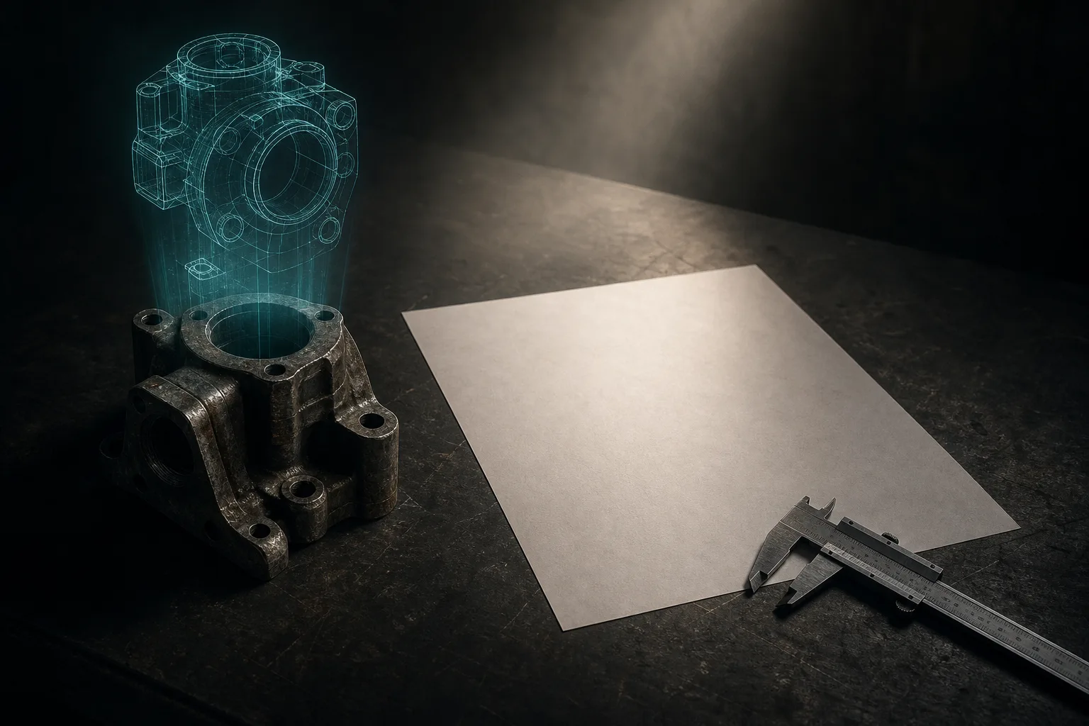
The starting point for many machining needs isn't a clean engineering drawing but a physical part held in the hand — no drawing, yet an urgent need to copy or refit it. That's when you need reverse engineering: working back from an existing object to the dimensions, tolerances, and material information needed for manufacturing. In practice, three scenarios are the most common:
- An old part is discontinued and the OEM no longer supplies it: a gear, bushing, or connecting rod on aging equipment breaks, the OEM has discontinued it or the lead time is too long, and all you can do is copy a spare from the one remaining old part.
- An overseas OEM won't provide drawings: for a consumable or structural part on an imported machine, the OEM won't release the drawing files for commercial reasons, so you have to measure it yourself for maintenance.
- A hand-made sample or trial piece: a master hand-fits a working prototype, or a customer brings in a 3D-printed concept sample and wants it "made like this," but there's no formal drawing anywhere in the process.
What the three share is that the shop needs clear geometry and specs before running the machine, and the fundamentals of manufacturing engineering remind us that a part's cost and manufacturability depend on the overall interplay of dimensions, tolerances, material, and process — not just "looking alike" (Kalpakjian & Schmid, 2020)[1]. So the first step in reverse engineering is turning the physical object into a drawing a shop can understand.
02Three routes for reverse engineering: hand measurement, 3D scanning, CT
There are three main routes for turning a sample into a drawing, each with its own range of fit, and in practice they're often mixed. The following is a qualitative comparison; the actual choice depends on part complexity, precision needs, and budget:
| Route | Best-suited parts | Characteristics and limits |
|---|---|---|
| Hand measurement (calipers, micrometers, height gauge, profile projector) | Regular plates, flanges, shafts, symmetric parts of revolution | Lowest cost, most reliable on key dimensions; but free-form surfaces are hard to describe fully, and it relies on the measurer's experience |
| 3D scanning (structured light, laser) | Free-form surfaces, impellers, shell parts, cosmetically complex parts | Quickly captures overall shape and a point cloud, good for grabbing form; deep holes and internal features can't be scanned, and absolute dimensions still need gauge calibration |
| Industrial CT (computed tomography) | Sealed cavities, internal channels, assemblies that can't be disassembled | Sees through internal structure with the most complete information; the highest equipment and cost, mostly for critical parts or when there's no other way |
A sensible approach is usually "scan the shape, calibrate key dimensions with gauges": first capture the overall geometry with 3D scanning, then go back to calipers and micrometers to calibrate important dimensions like mating faces one by one. Whichever route you take, the output of this stage is a point cloud or rough measurement data, which still needs an engineer to organize into a clearly annotated 2D drawing or 3D model before "redrawing" is truly complete.
03What to watch when measuring and redrawing: tolerances, material, surface finish
The most underestimated difficulty in reverse engineering is that you "can measure the dimension but can't infer the intent." A physical part won't tell you which dimension is a critical mating face and which is merely cosmetic — and that's exactly where engineering judgment is needed.
How to infer mating-face tolerances
What you measure off a sample is "the actual size of this one part," not "the design's required tolerance band." For the same hole, measuring 20.02 mm doesn't mean the drawing should read 20.02 — you first have to judge whether it's a functional hole mating with a shaft or a through-hole, then work back to a reasonable tolerance based on the fit type (clearance, transition, interference). Manufacturing-engineering texts stress that tolerances directly drive machining method and cost, and an over-tight tolerance makes cost rise sharply (Kalpakjian & Schmid, 2020)[1]. So when redrawing in reverse, mating faces should be judged and annotated by an engineer with reasonable tolerances, while non-mating free dimensions can use general tolerances — avoiding the needless high-precision requirements that come from "copying the measured value verbatim."
Material determination
Material determines cutting parameters, heat treatment, and strength, yet can't be measured with a ruler. You can make an initial judgment from clues like weight and density, magnetism, chip color and sparks, and hardness testing, doing a composition analysis where necessary. For spare-part refitting, you typically pick the same grade or a more suitable material by referring to the original's operating environment (load, corrosion, temperature), rather than blindly chasing an "exact match."
Surface-finish identification
Surface treatments like anodizing, galvanizing, black oxide, sandblasting, and hard anodizing affect both appearance color and dimensions (a plating layer has thickness). When reverse-engineering, identify the original's surface-treatment type and note: to copy a plated hole, the machined base-material dimension should subtract the plating thickness. All of this should be clearly annotated on the redrawn drawing, becoming the basis on which a shop can quote and work.
04Law and licensing: common-sense notes before you reverse-engineer
Reverse engineering is technically feasible, but copying someone else's part involves questions of rights ownership, so it's worth pausing to think before outsourcing. The following are general common-sense notes:
- Patents: a part's structure or function may be protected by a patent, and manufacturing a patent-protected product without authorization may constitute infringement.
- Copyright and styling: the drawing itself, and an original appearance/styling, may be protected by copyright or design-related rights.
- Trade secrets: obtaining someone else's undisclosed technical materials by improper means carries its own risk.
Generally, copying a discontinued old part for your own use or a replacement spare to repair existing equipment is relatively lower risk; while bulk-copying a product still under protection on the market to sell is clearly higher risk. The pragmatic approach is: before outsourcing, confirm you have a legitimate basis to use the part (for example, it's a repair part for your own equipment, you're licensed, or the rights have expired), and seek professional legal advice when the situation is unclear. This is only general common-sense guidance; specific cases should still be judged professionally.
05After redrawing: the long-term value of a digital drawing
The output of reverse engineering shouldn't be just "one drawing you can machine this time," but a reusable digital asset. Once a sample is turned into a structured electronic drawing file (such as DWG) and a 3D model, future reordering, deriving modified versions, and cross-shop quoting can all reuse it directly, without re-measuring every time.
A long-running research direction in the CNC field has been to make manufacturing information more open, interoperable, and exchangeable and reusable across different systems — rather than locked into a single machine or single format (Xu & Newman, 2006)[2]. That's the reason it's worth investing in "a clean, fully annotated digital drawing" when redrawing in reverse: it turns a part that once existed only physically into data that a CAD/CAM flow can read, verify, and machine over and over. For the trade-offs among different drawing formats, see Common CAD File Formats for CNC Machining and How to Choose.
From a data-interoperability standpoint, a good digital drawing can be read consistently by upstream and downstream systems, reducing the gaps of manual translation — consistent with the goals of an open, interoperable CNC information architecture (Xu & Newman, 2006)[2]. In other words, reverse redrawing doesn't just solve the order in front of you; it paves the way for later digitalized machining.
06AI drawing reading takes over: the starting point is a drawing, not a sample
Many people ask: "AI is so powerful — can't it just eat a part and spit out G-code?" Here we have to draw an honest line — this product's input is a 2D drawing (DWG first / PDF / photo as backup), not a physical sample. Turning a sample into a drawing is an upstream measurement and scanning service (hand measurement, 3D scanning, CT); that's the job of reverse engineering, not of AI drawing reading.
But the other side of that line is exactly where AI can dramatically accelerate things. Once you have a drawing, the machining prep that follows can be handed to AI: recognizing hole positions, threaded holes, and machining features, generating a 3D model, producing G-code per the shop's tool library and controller conditions, and verifying with cutting simulation and dimensional cross-checking. In other words, reverse engineering handles "redrawing the sample into a drawing," and AI handles "quickly turning the drawing into a verifiable machining program" — two stages, each in its role, connected end to end.
Worth noting: the tolerances and mating faces judged during reverse engineering are exactly the parts that most need human confirmation during AI drawing reading. The quality of machining prep depends on the completeness and correctness of the upstream drawing information (Kalpakjian & Schmid, 2020)[1] — annotate the mating faces, material, and surface finish clearly when redrawing, and AI's downstream recognition and verification will be accurate. To understand the capabilities and limits of AI drawing reading, see Snap a Photo and Build a 3D Model? What AI Drawing Recognition Can and Can't Do; for the data checklist when preparing to outsource, see The CNC Machining RFQ Guide. Once you have a clean drawing, AI can noticeably speed up the prep from redrawing to the machine — the core of the whole BestAI CAM machining-prep flow.
07FAQ
You have just one old part and no drawing at all — can you send it straight out for CNC machining?
In most cases you'll need to reverse a drawing or 3D model first. A shop needs clear dimensions, tolerances, and material before running the machine, and a physical sample alone makes it hard to tell which are the critical mating faces. You can turn the sample into a digital drawing through hand measurement or 3D scanning, have an engineer confirm the key dimensions, and only then enter the normal machining-prep flow.
Does reverse engineering always require 3D scanning or CT? Is hand measurement enough?
It depends on part complexity. Regular plates, flanges, and shafts are often best (and cheapest) done with calipers and micrometers by hand; free-form surfaces are better suited to 3D scanning for the overall shape; internal channels and sealed cavities are what call for industrial CT. The three are often mixed — scan the shape, calibrate key dimensions with gauges.
Could reverse-copying a sample infringe rights?
Possibly. A part may be patent-protected, and drawings and a specific styling may involve copyright or trade secrets. Reverse-making a spare for your own use or a replacement for a discontinued old part is usually lower risk, but bulk-copying someone else's protected product to sell is higher risk. Before outsourcing, confirm you have a legitimate basis to use the part, and seek professional legal advice where needed.
Once the drawing is redrawn, can AI take over machining directly?
Yes, but AI's starting point is a drawing, not the sample itself. This product's input is a 2D drawing (DWG first / PDF / photo as backup); turning a sample into a drawing is an upstream measurement and scanning service. Once a drawing exists, AI can recognize machining features, generate a 3D model and G-code, and run cutting simulation and dimensional cross-checking, greatly speeding up the prep after redrawing.
Get notified when new articles and video guides go live — no inbox spam, one-click unsubscribe. (newsletter in Chinese)
HAVE A DRAWING? LET AI TAKE OVER
Once reverse redrawing is done, let AI take over and speed up the prep
As soon as you have a 2D drawing (DWG / PDF / photo), we can help recognize features, generate the model and G-code, and run simulation and dimensional cross-checking.
Talk to a rollout consultant Training courses08References
- Kalpakjian, S., & Schmid, S. R. (2020). Manufacturing Engineering and Technology (8th ed.). Pearson.
- Xu, X. W., & Newman, S. T. (2006). Making CNC machine tools more open, interoperable and intelligent — a review of the technologies. Computers in Industry, 57(2), 141–152.