END MILL SELECTION GUIDE
How to Choose an End Mill? The Selection Logic for Flat, Ball and Bull-Nose Cutters
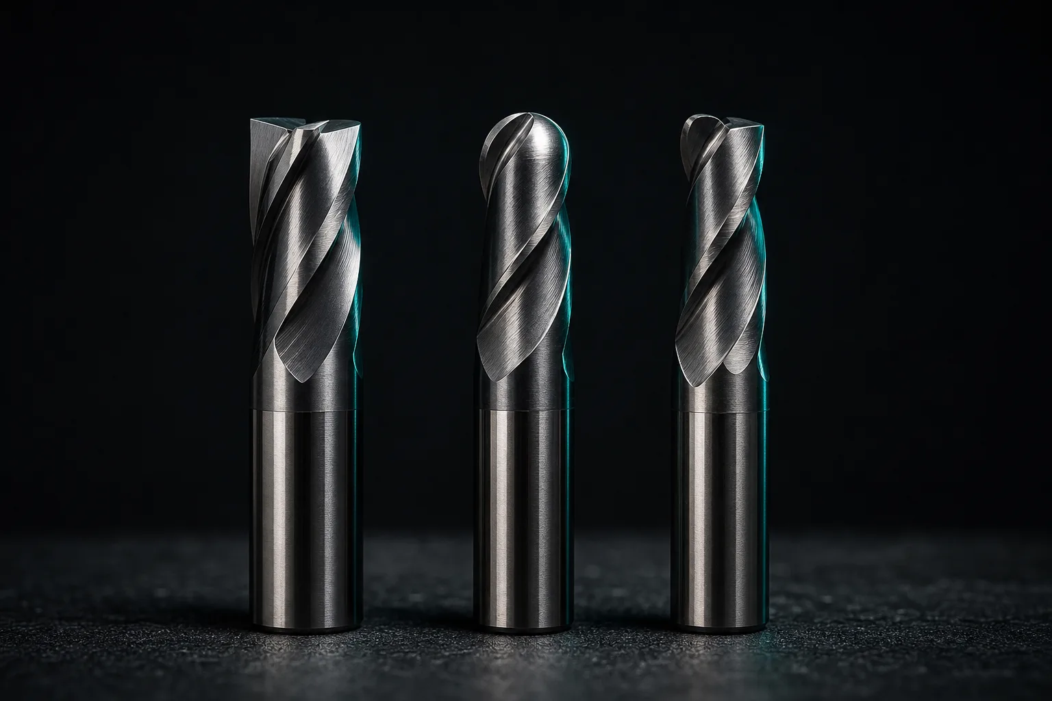
01The first step in choosing an end mill: look at what face you're machining
End mill selection looks like choosing among hundreds of specs, but the practical order of judgment is actually clear: first decide the cutter type (flat, ball or bull-nose), then diameter and flute count, and only last the substrate, coating and tool length. Cutter type comes first because it is set by the tip geometry, and the tip geometry maps directly to "is this feature a flat face, a curved surface, or does it need a radius"—get this step wrong and no amount of precise parameters afterward will produce the right shape.
Classic manufacturing-engineering textbooks note that the geometry and material selection of a milling cutter must consider the workpiece material, cutting conditions and the required surface integrity together, and no single cutter can do every machining task (Kalpakjian & Schmid, 2020)[1]. Choosing a cutter is not finding "the best cutter" but the most suitable cutter for "this operation"—which is why roughing and finishing of the same part often require different cutter types.
02Where flat, ball and bull-nose cutters fit: a comparison
The differences among the three main cutter types all come from the tip: the flat end mill has a square corner, the ball end mill a hemisphere, and the bull-nose cutter a square corner with a radius. This geometric difference determines the machining task each is best at.
| Cutter type | Tip geometry | Best-fit applications | Not suited for / limits |
|---|---|---|---|
| Flat end mill (square end mill) | Square-corner tip, flat bottom edge | Flat faces, straight side walls, square pockets, slotting, corner clearing; finishing vertical walls and floors | The square corner is a stress-concentration point and chips easily in heavy cutting; not suited for continuous 3D surfaces |
| Ball end mill (ball-nose) | Hemispherical tip | 3D free-form surfaces, mold contours, finishing of arc transitions; z-level and scan machining | The tip's centerline speed approaches zero, so it machines flat faces inefficiently and leaves marks—generally not used for finishing flats |
| Bull-nose cutter (corner-radius end mill) | Square corner with a radius (R) | Roughing with heavy stock removal, radiused side walls and floor transitions; balancing tip strength and surface transition | Cannot produce a fully sharp internal square corner (limited by the R); corner clearing still needs a flat end mill |
A common division of labor in practice is: the bull-nose cutter handles roughing, because the radius strengthens the tip and lets it withstand heavier stock removal; the flat end mill handles finishing of flats, straight walls and corner clearing, where a sharp square corner is needed; and the ball end mill is dedicated to surface finishing. A mold part with both curved surfaces and straight side walls may well use all three—which is exactly why cutter selection should be "by operation, not by part."
03Flute count and chip evacuation: fewer flutes for soft, more for hard
Once the cutter type is set, the second thing to decide is the flute count. Flute count affects two things—surface fineness and chip-evacuation space—and the two pull against each other.
- More flutes: more cuts per unit time at the same speed, a finer surface and a usable higher feed, but the flute space between edges shrinks and chips clog more easily.
- Fewer flutes: larger flutes and more chip room, suited to materials that produce long or sticky chips, but a relatively rougher surface.
The general rule by material is: for soft, chip-sticky materials like aluminum, copper and plastic, choose fewer flutes (e.g. 2 to 3) to keep chip-evacuation space and avoid chips packing into the flutes and "seizing" the tool; for hard materials like steel and stainless in shallow-cut finishing, more flutes trade for efficiency and surface quality. Slotting (slot width equal to the tool diameter) is the harshest case for chip evacuation—chips have nowhere to escape—so you usually deliberately choose fewer flutes and reduce the stock removed per pass. If chips can't get out and are re-cut, not only does the surface worsen, but wear and edge chipping accelerate sharply.
04Substrate and coating overview: what carbide and coatings do
Cutter type and flute count decide "how the shape is made"; substrate and coating decide "how long this cutter lasts and how fast it can run." This is only a qualitative overview and does not get into specific grade cross-references.
Tool body substrate
The most common tool body in milling today is carbide (cemented carbide), whose hardness and hot hardness are far superior to traditional high-speed steel (HSS), letting it withstand higher cutting speeds and temperatures—the mainstay for hard materials and volume production; HSS, with its better toughness and lower cost, still appears in low-speed, high-impact or small-batch cases. Textbooks note that the choice of tool material is essentially a trade-off between "hardness/wear resistance" and "toughness/chip resistance"—the harder and more wear-resistant the material, the more brittle it usually is[1].
Surface coating
A coating is a thin film plated on the tool surface (commonly nitride- and oxide-based coatings) to lower friction, raise surface hardness and insulate against heat, slowing wear and built-up edge formation. Different coatings suit different materials and environments: some emphasize high-temperature resistance, some anti-adhesion, some dry or high-speed cutting. In practice you don't need to memorize each coating's chemical formula—grasp the principle: a coating exists to make the tool "more wear- and heat-resistant," and the specific choice is left to the tool supplier's recommendation for the material being machined; a coating's benefit gradually disappears with wear, which connects to the tool-change judgment below.
05Tool length and rigidity: overhang, stiffness and chatter
The same end mill, clamped long or short, can give wildly different machining results. The key is the overhang—the distance the tip protrudes from the holder. The longer the overhang, the lower the bending rigidity of the shank, and the more easily chatter occurs during cutting.
Authoritative texts on metal-cutting mechanics and machine-tool vibration explain that regenerative chatter in milling stems from the dynamic flexibility of the tool–workpiece system: when the cutting excitation frequency approaches the system's natural frequency, the amplitude is amplified, leaving periodic tool marks, causing dimensional error, and in severe cases even breaking the tool (Altintas, 2012)[2]. And lengthening the overhang lowers both the rigidity and the natural frequency, making the system easier to excite into chatter—that is the mechanical reason "a tool extended too far chatters."
From this, a few shop-floor rules follow:
- As short as possible: choosing the shortest tool length and thickest shank that can still reach the target depth is the most direct way to raise rigidity.
- Extended tools only for deep pockets: switch to an extended tool only when a deep cavity is unavoidable, and correspondingly lower the cutting parameters and reduce stock removed per pass.
- Chatter has warning signs: an abnormally sharp squeal, regular wavy tool marks, or a suddenly worse surface are all chatter signals—stop and review tool length, speed and depth of cut.
For diagnosing chatter and machining defects, see CNC machining defect troubleshooting.
06Judging wear: when to change the tool
Tools are consumables, and even the best cutter wears. Changing too late lets a dull cutter raise cutting force, worsen the surface, throw dimensions off, and even chip and ruin the workpiece; changing too early inflates tool cost. Judging when to change the tool is a lesson as important as choosing the cutter in the first place.
A CIRP review of machining monitoring notes that tool condition can be inferred indirectly through multiple signals—cutting force, spindle power, vibration and acoustic emission all change as wear progresses, and these signals are the basis on which "advanced machining monitoring" estimates tool life and degree of wear (Teti et al., 2010)[3]. On the floor, observable signs of wear include:
- Surface degradation: the once-shiny machined face develops drag marks, bright edges, or more burrs.
- Change in sound and vibration: the cutting sound turns dull or sharp, or irregular chatter appears.
- Change in chip color and form: chips discolor abnormally (overheating) or become irregular in shape.
- Dimensional drift: in continuous machining, the bore diameter or wall thickness gradually drifts from the tolerance center.
The mature approach is to bring "tool life" into process management: for critical operations, record each tool's accumulated cutting time or number of parts machined, and proactively change the tool as it nears its empirical life rather than waiting for a problem. This "manage tools with data" mindset is exactly what documenting a tool library sets out to solve.
07How documenting a tool library lets AI pick the right cutter
AI can help draft all the selection logic above—but on one condition: AI can only choose from the tools the shop actually owns. If tool data is scattered in veterans' heads and paper lists, AI has no way to know which tools the shop has or how long each is when it generates G-code, and it cannot apply the correct tool-length offset. This is precisely the value of building tools into a structured tool library.
A tool library AI can actually use must contain, for each tool, at least: the tool code, type (flat/ball/bull-nose), diameter and corner R, flute count, substrate and coating, standard clamped length and maximum usable overhang. With these fields, when AI generates the machining program and cutting simulation, it can:
- Select tools that really exist: pick the right cutter type and diameter by machining feature, rather than specifying a tool the shop doesn't have out of thin air.
- Apply the correct tool-length offset: compute the tool-length offset from the documented standard length, reducing tool-length setup errors and crash risk.
- Include rigidity and travel checks: based on overhang and machine travel/speed limits, avoid producing a program beyond the machine's capability.
- Gradually approach the shop's habits: combined with historically successful programs, AI's cutter choices come ever closer to the veterans' way.
It bears emphasizing that the tools and program AI selects are still "drafts": tolerances, datums, special methods and the final confirmation before the job runs remain in the hands of on-site professionals (human-in-the-loop). AI's role is to turn "choosing cutters by experience" into a process that "has a database to query, can be simulated, and can be verified," so that cutter selection is no longer locked in a few people's heads. To look further upstream at the relationship between cutter type and operation, return to this blog's pillar article The complete guide to CNC automated programming to understand the whole prep flow from drawing to G-code.
08FAQ
What is the main difference between flat, ball and bull-nose end mills?
The difference is in the tip geometry and the machining task it dictates. A flat end mill has square-corner tips and suits flat faces, straight side walls and slotting; a ball end mill has a hemispherical tip and suits 3D surfaces and mold finishing; a bull-nose cutter has a radius on the square corner, balancing strength and transition, and is often used for roughing and radiused side walls. Ask "is this face flat, curved, or does it need a radius" first, then decide the cutter type.
Are more flutes on an end mill always better?
No. More flutes give a finer surface but less chip space; fewer flutes evacuate chips better but leave a rougher surface. Soft, chip-sticky materials like aluminum and plastic often use fewer flutes to keep the flute space open; hard materials like steel and stainless in shallow cutting can use more flutes for efficiency. Flute count is a trade-off between "chip-evacuation space" and "surface fineness," judged together with material and depth of cut.
Why is a longer tool overhang more prone to chatter?
The longer the overhang, the lower the shank's bending rigidity and natural frequency, making it easier to excite regenerative chatter during cutting—causing tool marks, dimensional error, or even a broken tool. The practical rule is "as short as possible": choose the shortest tool length and thickest shank that can still reach the depth, and only switch to an extended tool—at reduced cutting parameters—for deep pockets.
How does documenting a tool library help AI pick a cutter?
AI can only choose from the tools the shop actually owns. Once you build a structured tool library with tool code, type, diameter, flute count, standard length and coating, AI will select tools that really exist and apply the correct tool-length offset when it generates G-code and simulation, reducing tool-length setup errors and crash risk; the more complete the records, the closer AI's cutter choices come to the veterans' habits.
Get notified when new articles and video reviews go live—no inbox flooding, one-click unsubscribe.
LET AI PICK THE RIGHT TOOL
Turn cutter-selection experience into a tool library AI can query
From cutter type, flute count and coating to tool length and rigidity, we help build your shop's cutter-selection logic into a structured tool library, so AI picks the right cutter and applies the right offset when it generates G-code.
Contact an implementation advisor Training courses09References
- Kalpakjian, S., & Schmid, S. R. (2020). Manufacturing Engineering and Technology (8th ed.). Pearson.
- Altintas, Y. (2012). Manufacturing Automation: Metal Cutting Mechanics, Machine Tool Vibrations, and CNC Design (2nd ed.). Cambridge University Press.
- Teti, R., Jemielniak, K., O'Donnell, G., & Dornfeld, D. (2010). Advanced monitoring of machining operations. CIRP Annals, 59(2), 717–739.